
Cam Roller Pin With Transverse Grooves

a technology of cam rollers and roller pins, which is applied in the direction of couplings, machines/engines, fuel injecting pumps, etc., can solve the problems of imperfect and non-uniform contact area between cam rollers, roller pin bends, and cam rollers exposed to extremely high loading, so as to improve the contact and interface, reduce localized contact pressure, and be stronger. durable

Active Publication Date: 2007-12-06
WOODWARD GOVERNOR CO
View PDF5 Cites 21 Cited by
  • Summary
  • Abstract
  • Description
  • Claims
  • Application Information

AI Technical Summary

Benefits of technology

[0005]The present invention provides a roller pin that may be manufactured from stronger, more durable materials without increasing wear on a carried cam roller by reducing localized contact pressure between the roller pin and a carried cam roller. In an embodiment of a roller pin of the present invention run-in time between the cam roller and roller pin is significantly reduced or all-together eliminated. To provide such a roller pin, the roller pin includes a plurality of grooves that allow for localized bending to improve the contact and interface between the cam roller and the roller pin.

Problems solved by technology

In pumps such as high pressure pumps, the cam roller is exposed to extremely high loading.
The high loading on the cam roller imposes a bending moment on the roller pin carrying the cam roller, thereby causing the roller pin to bend.
The bending of the roller pin without corresponding bending of the cam roller creates an imperfect and non-uniform contact area between the cam roller and roller pin.
As a result, non-uniform contact pressure is applied at the edges of the contact area.
This abnormal contact pressure near the edges of the contact area causes the cam roller to be overloaded and causes localized damage and wear to the inside diameter of the cam roller and outside diameter of the roller pin.
Current designs often require a “run-in” period during which the pump is ran to control the roller pin initial wear rate to reduce the non-uniformity between the roller pin and cam roller, and thereby reduce high end load pressures.
The use of softer metals reduces the amount of run-in required because of the increased local wear rate and lower strength of the softer metals.
Under the high contact pressure near the ends of the cam roller, the use of softer metals results in an increased rate of wear on the roller pin, thereby reducing the overall operating life of the tappet assembly before repair is required.

Method used


Image

  • Cam Roller Pin With Transverse Grooves
  • Cam Roller Pin With Transverse Grooves
  • Cam Roller Pin With Transverse Grooves

Examples


Embodiment Construction

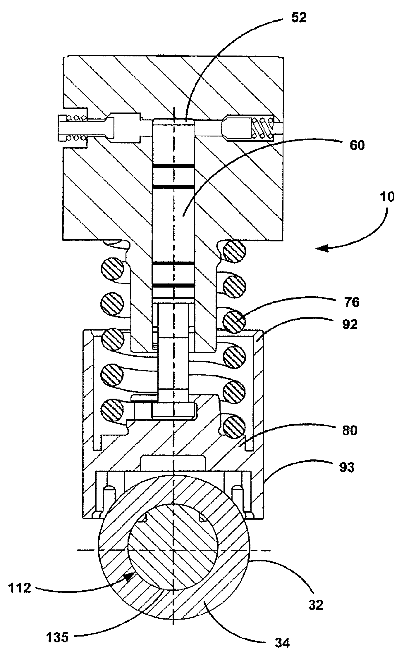
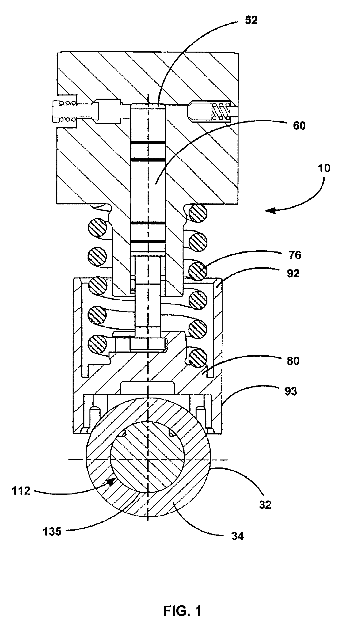
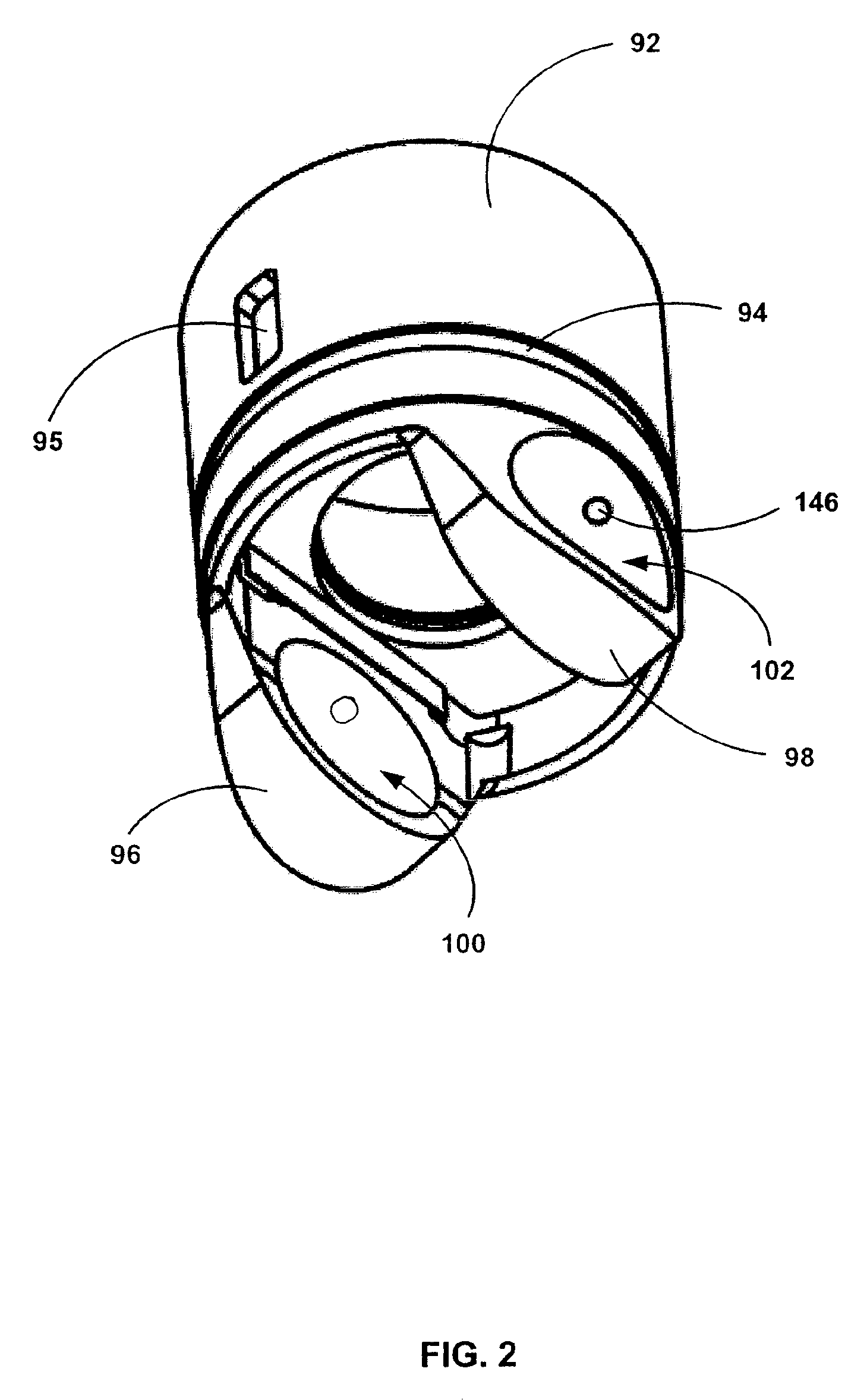
[0020]A brief overview of a typical environment in which the invention operates shall be described to help in understanding the invention. Turning to the drawings, and particularly to FIG. 1, wherein like reference numerals refer to like elements, a tappet assembly 10, particularly suited for use in pumps to pressurize and pump fluid is illustrated. It is noted that the invention may be used in other operating environments. The tappet assembly 10 converts a rotational input motion to a linear fluid pumping action for the pump. Typically, the tappet assembly 10 is located and secured within a cylindrical bore of a pump housing. A single pump may include a plurality of tappet assemblies secured therein to provide a sufficient outflow rate for a given application.

[0021]As is well known in the art, to convert the rotational motion to a linear motion, the pump includes a rotatable camshaft having a lobe that extends radially outward from the camshaft. The lobe has an eccentric radial pro...


PUM


Abstract

A roller pin for carrying a cam roller in a tappet assembly is provided. The roller pin providing reduced run in time and reduced peak and localized contact pressure between the cam roller and roller pin. The roller pin comprises a substantially cylindrical shaft having a length, a first end and a second end. The length extends from the first end to the second end. The shaft includes a plurality of grooves axially spaced apart and extending in a direction being transverse to the length. The plurality of grooves located proximate the first and second ends and extending only partially the circumference of the shaft.

Description

FIELD OF THE INVENTION[0001]The present invention relates generally to rollers and roller pins, and more particularly to cam rollers and cam roller pins.BACKGROUND OF THE INVENTION[0002]Many cam driven piston type pumps use tappet assemblies for pumping fluid. A tappet assembly includes a cam roller that is rotatably mounted on a roller pin. Typically, the cam roller follows an outer periphery of a rotating eccentric camshaft of the pump. The eccentric peripheral shape causes the cam roller to be actuated in a cyclical motion away from and towards the camshaft as it rotates. As the cam roller is cyclically actuated, the motion is translated to a plunger. During one portion of a pumping cycle, fluid is drawn by the plunger movement into a pumping chamber. During the second portion of the pumping cycle, the plunger pumps the fluid out of the chamber. Such tappet assemblies are known in the art.[0003]In pumps such as high pressure pumps, the cam roller is exposed to extremely high load...

Claims


Application Information

Patent Timeline
IPC IPC(8): F01L1/14
CPCF01L1/146F01L2105/00F02M2200/9053F02M59/44F02M2200/02F02M59/102F02M63/0001F01L2305/00
Inventor BRINKS, BARRY T.
Owner WOODWARD GOVERNOR CO
Learn More