
Valved, microwell cell-culture device and method

Active Publication Date: 2007-11-29
MILLIPORE CORP
View PDF99 Cites 96 Cited by
  • Summary
  • Abstract
  • Description
  • Claims
  • Application Information

AI Technical Summary

Benefits of technology

[0017] In another aspect, the invention includes a valved microfluidics device having a substrate, a microchannel through which liquid can be moved from one station to another within the device, and a pneumatic microvalve adapted to be switched between open and closed states to control the flow of fluid through a microchannel. The microchannel is formed of (i) two or more flexible membranes forming wall portions in a valved region of the microchannel, including a primary membrane and one or more secondary membranes that are each joined to the primary membrane at a common edge, and (ii) a chamber formed in the substrate, separated from the microchannel by the primary membrane and adapted to receive a positive or negative fluid pressure, thus to deform the primary membrane. Deformation of the primary membrane causes the secondary membrane(s) to deform, and the combined deformation of the primary and secondary membranes is effective to switch the condition of the valve between its open and closed states.
[0018] The device may include, for each secondary membrane, a recess formed in the substrate into which the secondary membrane is deflected when deformed. The flexible membranes may include a top-wall primary membrane and a pair of opposite side-wall secondary membranes, with the valved region of the microchannel, with the valve in its open state, being substantially rectangular. The height to width ratio of the rectangular microchannel may be at least about 0.5 to 1.0. The application of positive pressure to the chamber, to place the valve in its closed state, may cause the primary membrane to bow outwardly into the channel, and the secondary membranes to bend outwardly at their common edges with the primary membrane, into the associated recesses, thus to enhance the extent of sealing between the primary membrane and the two secondary membranes as the primary membrane is deformed.

Problems solved by technology

Various limitations associated with prior art devices include (i) the requirement for bulky robotics to populate the wells in the device, (ii) difficulty in preventing microfluidics structures from being blocked by cell growth within the structures, (iii) inability to sustain uniform culture conditions over an extended assay period, (iv) inability to achieve and alter cell-culture conditions at the level of individual wells, and (v) difficulty in creating the necessary microfluidics structures efficiently by microfabrication.

Method used


Image

  • Valved, microwell cell-culture device and method
  • Valved, microwell cell-culture device and method
  • Valved, microwell cell-culture device and method

Examples


Embodiment Construction

A. Definitions

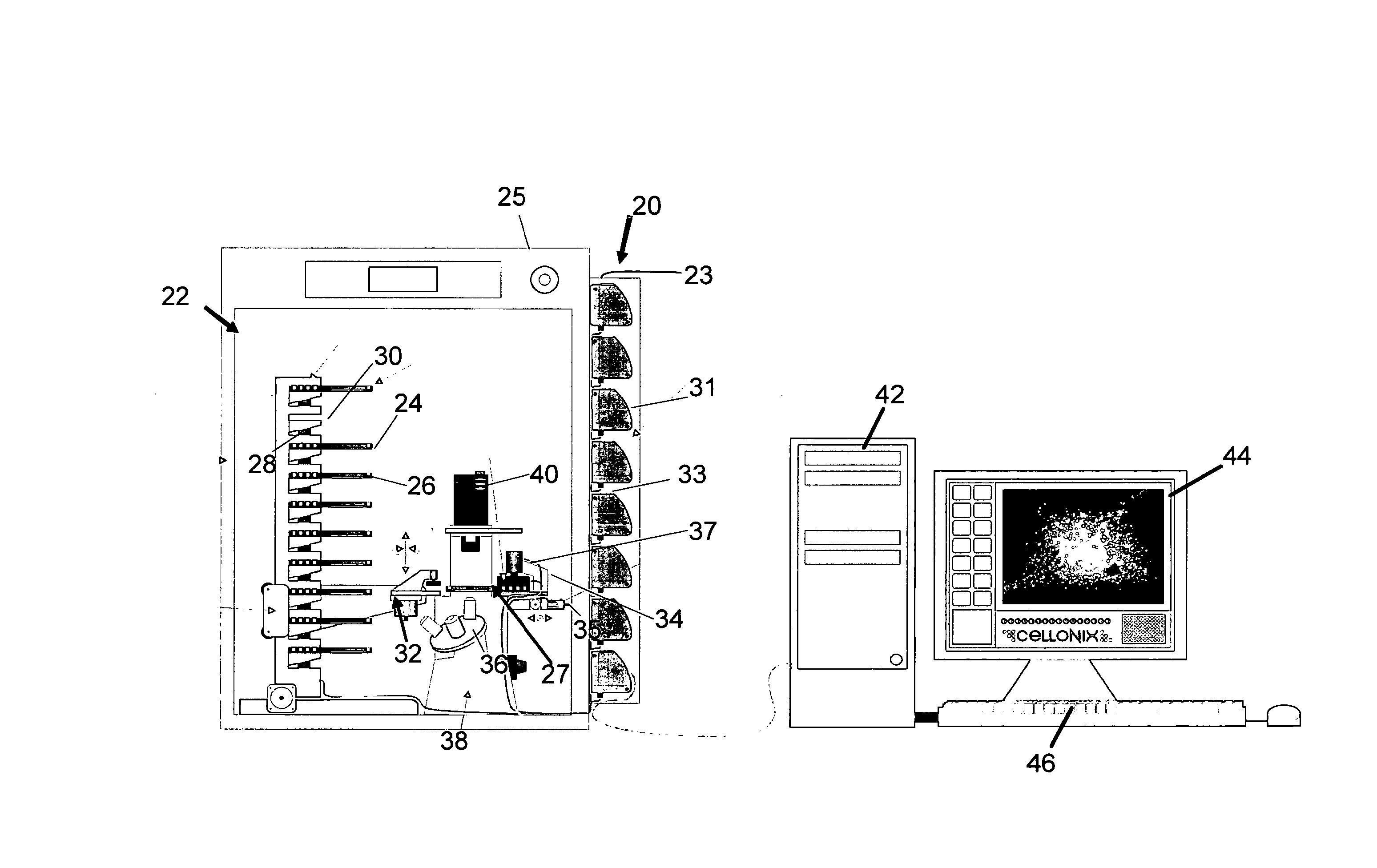
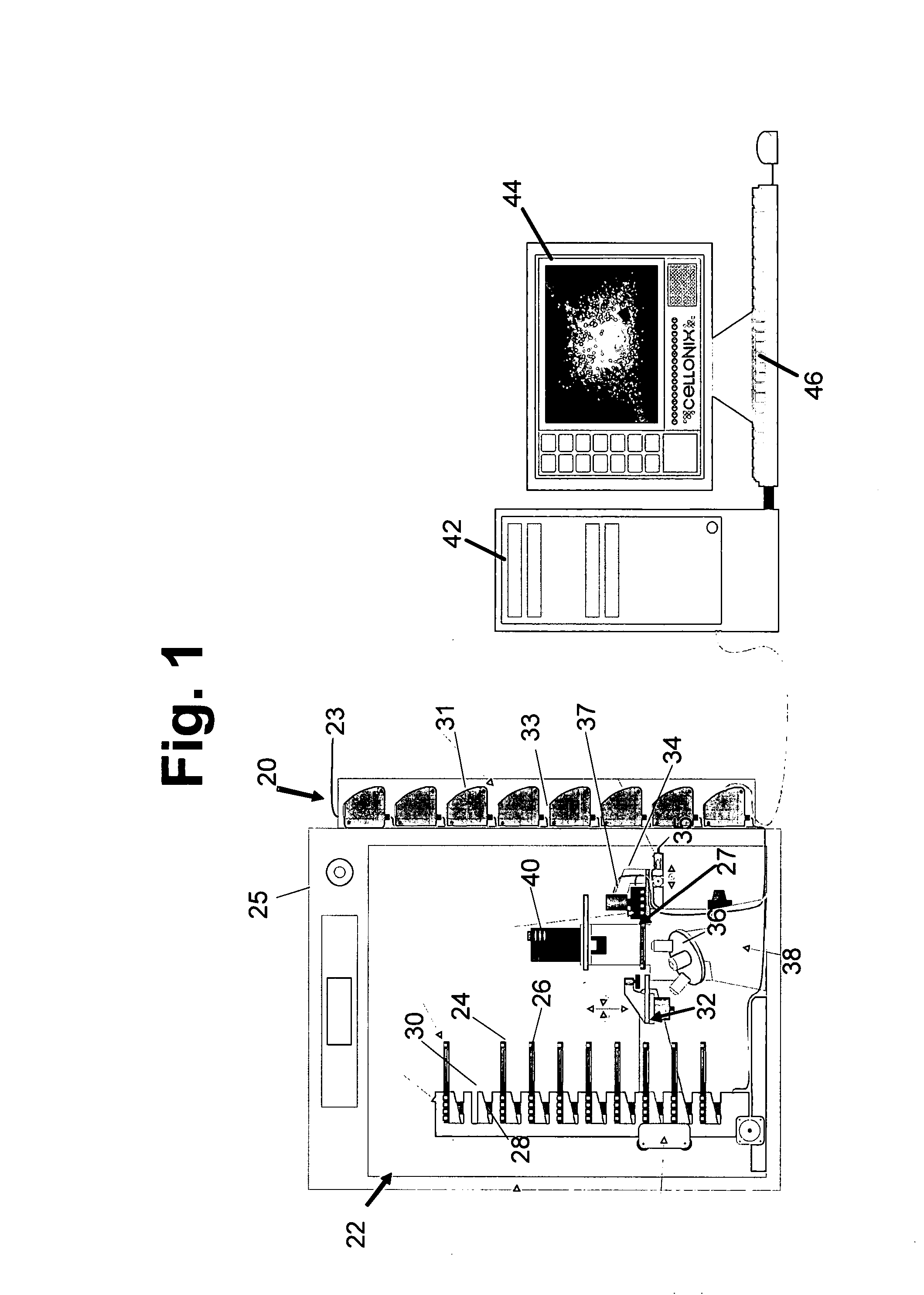
[0044] A “particle” refers to biological cells, such as mammalian or bacterial cells, viral particles, or liposomal or other particles that may be subject to assay in accordance with the invention. Such particles have minimum dimensions between about 50-100 nm, and may be as large as 20 microns or more. When used to describe a cell assay in accordance with the invention, the terms “particles” and “cells” may be used interchangeably.

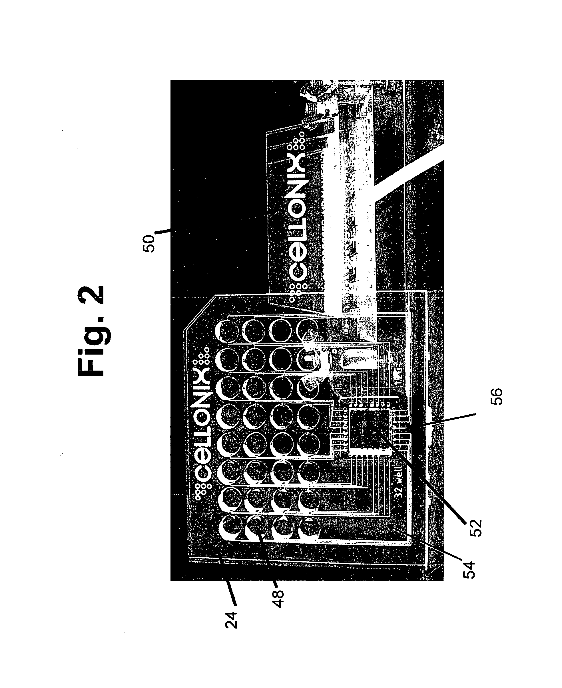
[0045] A “microwell” refers to a micro-scale chamber able to accommodate a plurality of particles. A microwell is typically cylindrical in shape and has diameter and depth dimensions in a preferred embodiment of between 100 and 1500 microns, and 10 and 500 microns, respectively. When used to refer to a microwell within the microwell array device of the invention, the term “well” and “microwell” are used interchangeably.

[0046] A “microchannel” refers to a micron-scale channel used for connecting a station in the device of the invention with...


PUM

PropertyMeasurementUnit
Fractionaaaaaaaaaa
Heightaaaaaaaaaa
Pressureaaaaaaaaaa

Abstract

A valved microfluidics device, microfluidics cell-culture device and system incorporating the devices are disclosed. The valved microfluidics device includes a substrate, a microchannel through which liquid can be moved from one station to another within the device, and a pneumatic microvalve adapted to be switched between open and closed states to control the flow of fluid through a microchannel. The microvalve is formed of three flexible membranes, one of which is responsive to pneumatic pressure applied to the valve and the other two of which deform to produce a more sealable channel cross-section. The cell culture device provides valving to allow controlled loading of cells into the individual well of the device, and exchange of cell-culture components in the wells.

Description

[0001] This patent application claims priority to U.S. provisional patent application No. 60 / 756,399 filed on Jan. 4, 2006, which is incorporated in its entirety herein by reference.FIELD OF THE INVENTION [0002] The present invention relates to a microwell device and method, and in particular, to a valved microwell array device designed for high throughput cell culture assays, to microvalve for use in the device, and to methods for making the valve and device. BACKGROUND OF THE INVENTION [0003] There is a growing demand in the drug discovery and related fields for high throughput cell culture systems, that is, systems capable of supporting large numbers of cell-culture assays in parallel. For a variety of reasons, it would be desirable to conduct large-scale cell-culture assays in a microfluidics device having an array or microwells and microfluidics structure for populating and feeding the wells. One major advantage of microfluidic cell culture is the possibility to mimic in vivo c...

Claims


Application Information

Patent Timeline
IPC IPC(8): C12M1/34
CPCB01L3/5025G01N33/54366B01L3/502738B01L2200/12B01L2300/0681B01L2300/0816B01L2300/10B01L2300/123B01L2400/0481B01L2400/0655C12M23/12C12M23/16C12M29/10C12M41/00C12M41/48F16K99/0001F16K99/0015F16K99/0059F16K2099/0074F16K2099/0078F16K2099/0084G01N2035/00158B29C65/002C12M29/14F16K27/0236B01L3/502707B01L3/502715B01L3/50273B01L3/502746B01L2300/0819B01L2300/14B01L2400/0487C12Q1/025G01N33/5008Y10T137/2202
Inventor HUNG, PAUL JU-SUNGLEE, PHILIP JANMIN
Owner MILLIPORE CORP
Learn More