
Light expanding system for producing a planar light beam from point light sources

a technology of point light source and light expansion system, which is applied in the direction of planar/plate-like light guides, lighting and heating apparatus, instruments, etc., can solve the problems of not being suitable for sunlight-readable displays, and unable to provide adequate brightness for certain large-area lighting

Inactive Publication Date: 2007-11-29
CLIO TECH
View PDF17 Cites 77 Cited by
  • Summary
  • Abstract
  • Description
  • Claims
  • Application Information

AI Technical Summary

Benefits of technology

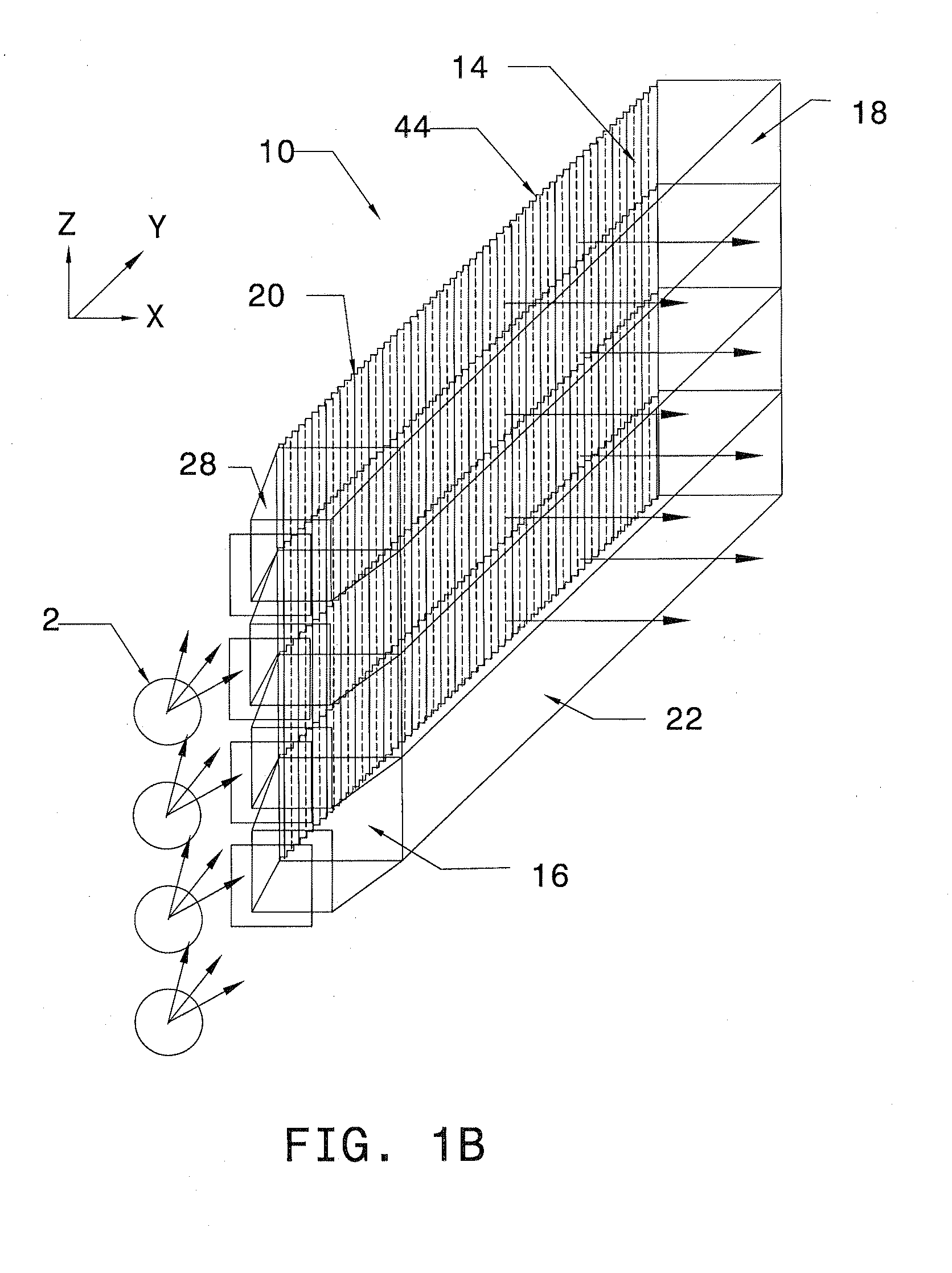
[0008]According to the invention, a light expanding system is used to convert light generated from point-like light sources into a planar light beam. The planar light beam can be collimated in one or more dimensions. As compared to conventional lens and mirror collimating systems, the system according to the invention has a reduced volume. The lighting system in this invention is capable of illuminating a given area with light of different spectrum, but similar angular distribution. It can therefore achieve multi-mode operation.
[0010]According to another embodiment of the invention, a system as described immediately above further includes a prismatic, or holographic, diffuser film which changes the propagation direction of light beams transmitting through this film. This diffuser film expands the images of the point light sources, and therefore improves the uniformity of the backlight system. In this embodiment, this prismatic, or holographic, diffuser is placed between the beam collector and the light guide.
[0013]According to yet another embodiment of the invention, a system includes structure as described in the first embodiment, but with a plurality of microprisms positioned immediately adjacent to the third surface. The axis of the microprisms is essentially perpendicular to that of the microprisms on the second surface. Adding the prisms to the third surface of the light pipe allows multi-mode operation of the backlight with LEDs.

Problems solved by technology

The backlight systems described in applicants' earlier inventions that convert light beam from point-like light sources, such as LEDs use only a small number of light sources, and therefore cannot provide adequate brightness for certain large area lighting.
Specifically, a backlighting system made with the earlier technology is not suitable for sunlight-readable displays.

Method used


Image

  • Light expanding system for producing a planar light beam from point light sources
  • Light expanding system for producing a planar light beam from point light sources
  • Light expanding system for producing a planar light beam from point light sources

Examples


Embodiment Construction

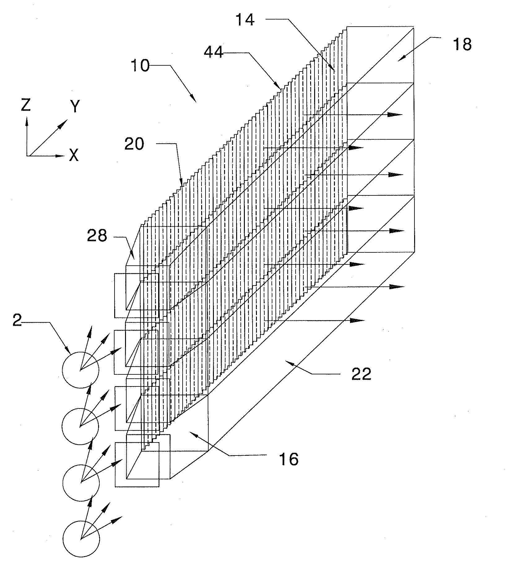
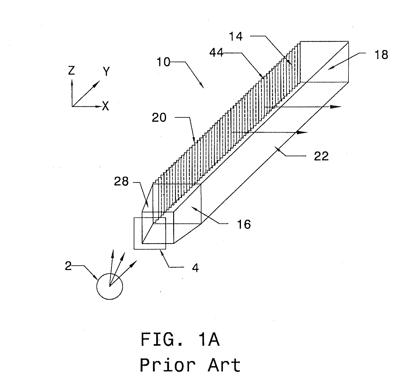
[0042]Turning now to the drawings, wherein like components are designed by like reference numerals throughout the various figures, attention is first directed to FIG. 1A which shows a lighting system converting light output from a point-like light source 2 into a linear light beam. This light expanding system 10, discussed in detail in U.S. Pat. No. 5,506,929, includes a beam collector 28 and a beam expanding light pipe 14. A light filter 4, which can be a color filter, or heat filter, is placed between the light source 2 and the light expanding system 10. The filter 4, however, is not required for the operation of the light expanding system 10. A plurality of microprisms 44 are positioned immediately adjacent to a reflecting surface 20 of the beam expanding light pipe 14. Light that enters the beam expanding light pipe 14, through the entering surface 16 of the beam expanding light pipe 14, is directed by the microprisms 44, so that the light exits the beam expanding light pipe 14 ...


PUM


Abstract

A light expanding system for converting light beams generated from point-like light sources into a collimated planar light beam is described herein. The light expanding system is especially suitable for backlighting a liquid crystal flat panel display or other such arrangement requiring backlighting with LEDs as the light source. According to an embodiment of the invention, a system for producing a planar light beam includes a light pipe with microprisms on one of its surfaces, and a beam collector which has microprisms in a plane perpendicular to the microprisms in the light guide. According to another embodiment, the light guide has microprisms on two opposite surfaces, and is capable of multiple mode operation. This multiple mode backlight is capable of illuminating a given active area uniformly with light of different spectrum.

Description

BACKGROUND OF THE INVENTION[0001]1. Field of the Invention[0002]The invention relates generally to a backlighting system especially suitable for use with liquid crystal displays. In particular, it converts light from point like light sources, such as LEDs into a planar light source. A light pipe assembly in accordance with this invention is suitable for multi-mode operation that can illuminate the display area with light of a different spectrum, and can use LEDs of different colors for display lighting.[0003]2. Description of the Prior Art[0004]Liquid crystal displays are commonly used in portable computer systems, televisions, and other electronic display devices. Most of the large area, high performance LCDs require a source of lighting for operation. Backlighting the LCD has become the most popular source of light in LCD devices. Our earlier invention, described in U.S. Pat. Nos. 5,359,691; 5,390,276 and 5,854,872, provides a very efficient backlighting and can also provide colli...

Claims


Application Information

Patent Timeline
Patent Type & Authority Applications(United States)
IPC IPC(8): F21V7/04
CPCG02B6/0018G02B6/002G02B6/0068G02B6/0028G02B6/0038G02B6/0025
Inventor TAI, CHEN-YUTAI, PING-KAUNG
Owner CLIO TECH
Learn More