
Image processing apparatus, printing apparatus and image processing method

Active Publication Date: 2007-11-29
CANON KK
View PDF17 Cites 8 Cited by
  • Summary
  • Abstract
  • Description
  • Claims
  • Application Information

AI Technical Summary

Benefits of technology

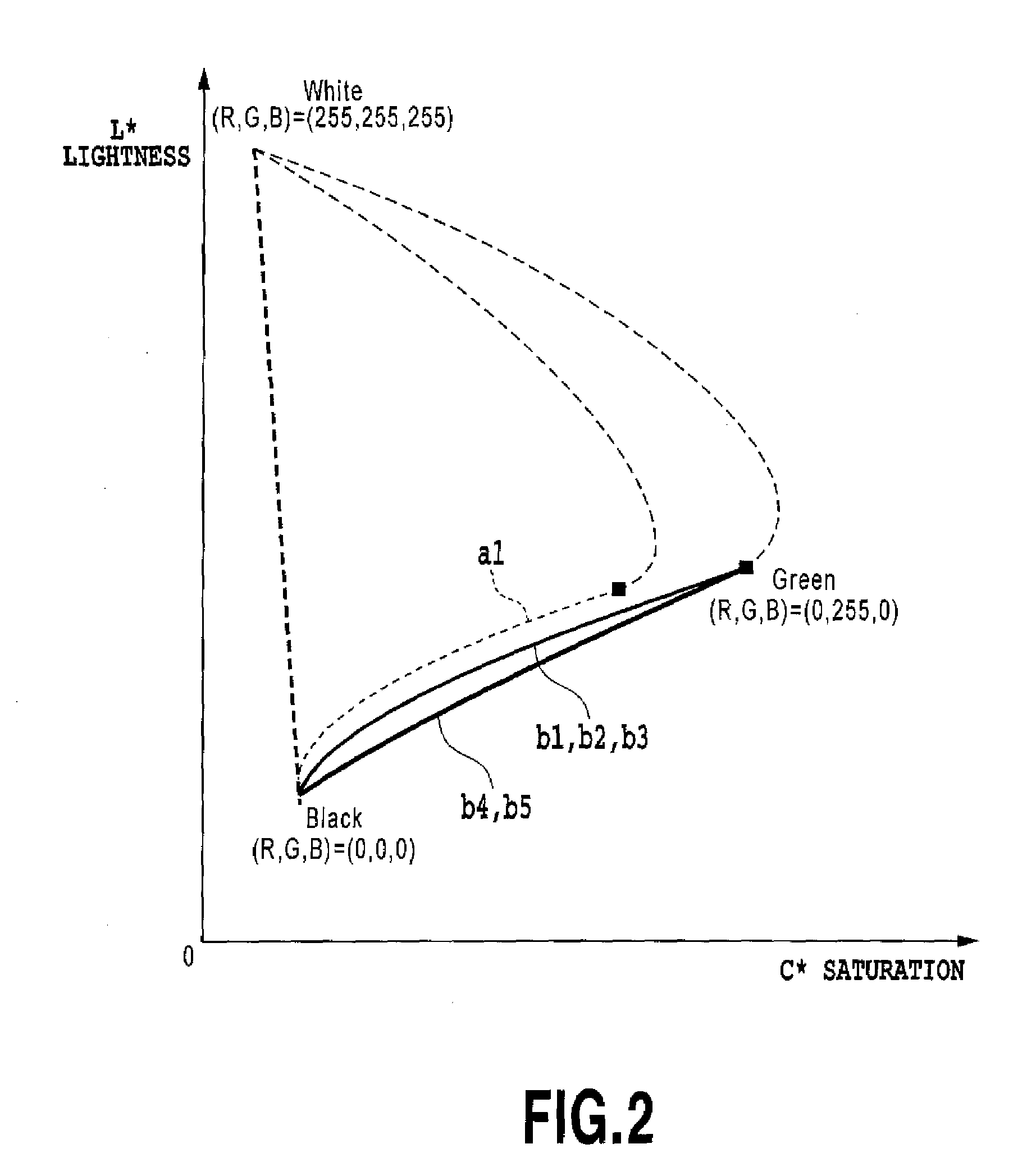
[0021]An object of the present invention is to provide an image processing apparatus, a printing apparatus and an image processing method which are capable of realizing color reproduction with high chroma at a low lightness portion by using a recording material of an appropriate complementary color for a particular color recording material for reproducing the low lightness portion.
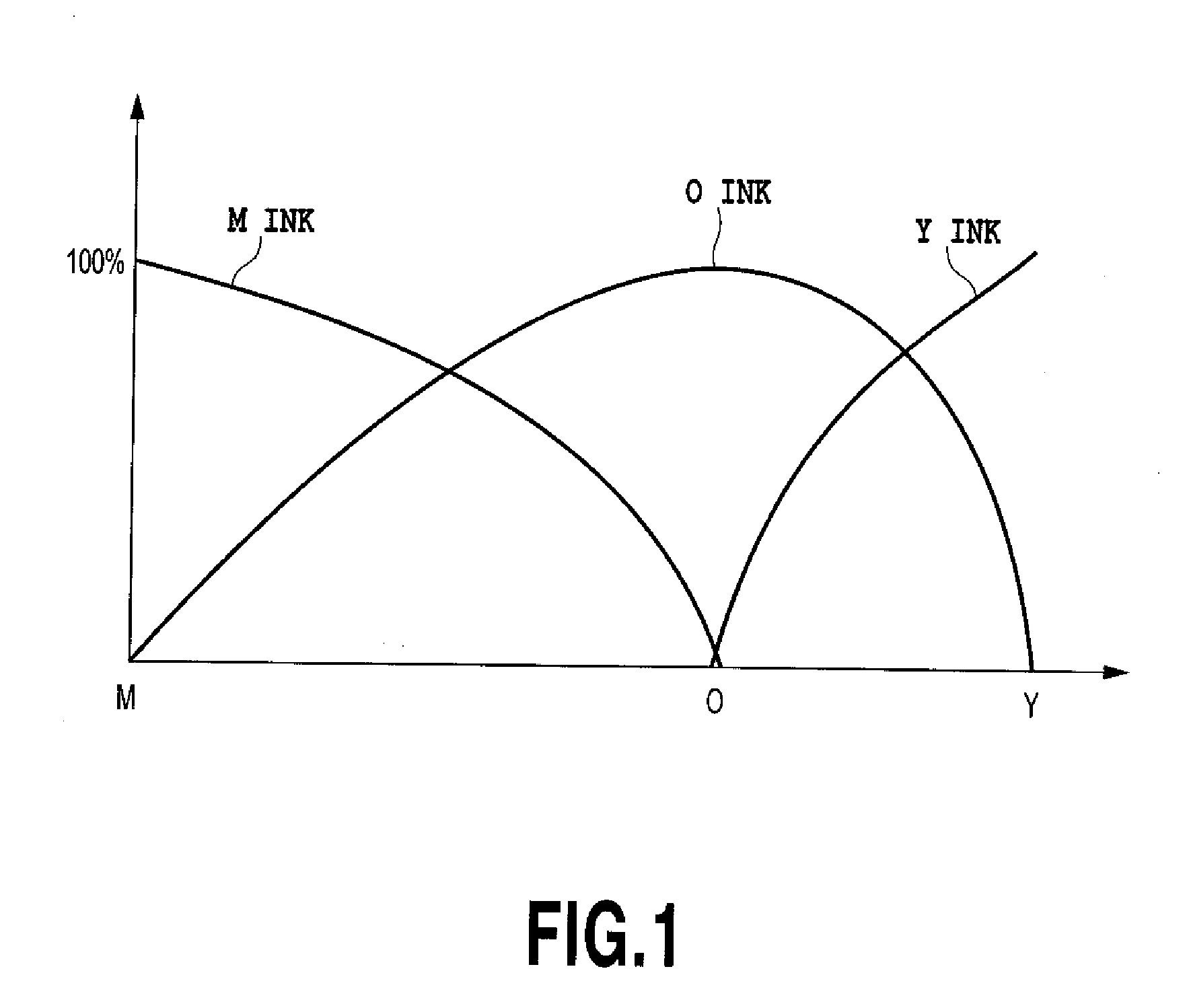
[0025]According to the above configuration, when reproducing a color in a low lightness by using a first particular color recording material, a second particular color recording material is used as a complementary color, the lightness can be effectively lowered and the lowering of the chroma can be prevented. In consequence, even at a dark portion in a color reproduction region reproduced by the particular color recording material, the color reproduction with high chroma can be made.

Problems solved by technology

However, the above stated basic colors and quasi-basic colors have the limitation in reproducing color and it is hard to reproduce a relative bright color therewith.
The color separation of conventional arts described above is, however, not sufficient in view of increasing the chroma at a low lightness portion.
Therefore, an improvement of sufficient chroma at the dark portion can not be expected.
Therefore, likewise, an improvement of sufficient chroma at the dark portion can not be expected.
However, since the color separation uses the basic color and the quasi-basic color as the complementary color components, there is a case where these complementary colors do not become idealized complementary colors for the particular color in terms of a reflection spectrum.
As a result, the color reproduction where the lightness is sufficiently lowered and at the same time, reduction of the chroma is prevented may not be realized.
Thus, it may not be possible to realize high chroma at the dark portion.

Method used


Image

  • Image processing apparatus, printing apparatus and image processing method
  • Image processing apparatus, printing apparatus and image processing method
  • Image processing apparatus, printing apparatus and image processing method

Examples


first embodiment

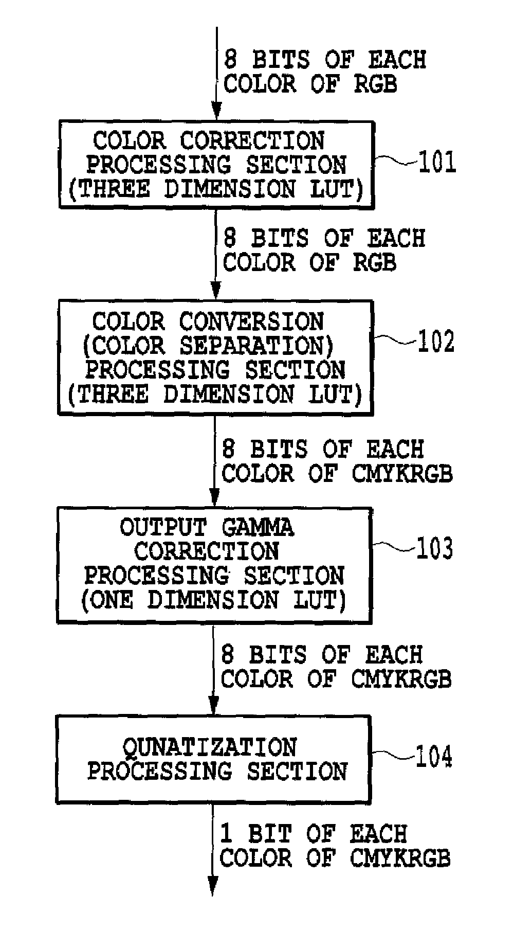
[0101]FIG. 15 is a diagram showing a schematic configuration of a printing system having an ink jet printer and a host computer in an embodiment of the present invention. In FIG. 15, an ink jet printer 13 is provided with a plurality (seven colors) of head cartridges (printing portion) 1A, 1B, 1C, 1D, 1E, 1F and 1G detachably mounted on a carriage 2. It should be noted that in a case of showing the entirety of the plurality of the printing portions 1A to 1G or any one thereof, it is simply shown with the printing portion (print head or head cartridge) 1.

[0102]Each cartridge 1 includes an ink tank portion in the upper side and a print head portion (ink eject portion) in the lower side to form the structure of uniting the print head portion and the ink tank. It should be noted that needless to say, the printing portion and the ink tank may be mutually detached. Each printing portion 1 positions a carriage 2 and is mounted to be replaceable. Each printing portion 1 is provided with a c...

modification 1

(Modification 1)

[0190]A first modification of the embodiment is an example of color separation B5 of adjusting the hue on G-K line with the complementary color components of R, Gry and K.

[0191]FIG. 32 is a diagram showing color separation for the G-K line in FIG. 18 according to a modification of the present invention, using ink of six colors of C, Y, K, R, G and Gry including the particular color G ink and using ink of complementary color components of Gry, R and K. This color separation shows an example that the G-K line is adjusted in such a manner as to be substantially linear on an a* b* plane.

[0192]The color separation B5 shown in FIG. 32 is basically the same as the color separation in the embodiment shown in FIG. 28. However, when Gry ink is used from the vicinity of the device secondary color G point and the particular color R ink begin to be added from a point where the granular feeling become unnoticeable as the complementary color component.

[0193]The above color separati...

modification 2

(Modification 2)

[0195]FIG. 33 is a diagram showing color separation in a second modification of the above embodiment. This color separation uses ink of five colors of M, Y, K, R, and G including the particular color R ink and uses inks of G and K as complementary color components for the color reproduction on R-K line in FIG. 18.

[0196]The color separation according to this modification, in which an object hue (line) is different, uses the particular color R ink as the pure color component and the particular color G ink as the complementary color component and is similar to the color separation shown in FIG. 28 in terms of a basic configuration.

[0197]The color separation method according to the present invention is applied to not only the G-K line but also can be broadened and applied to the other hue easily.

[0198]Examples of a combination of the particular color used for each of the pure color and the complementary color include G-R (O), R (O)-G as described above and further G-B (V...


PUM


Abstract

Color production with high chroma in a low lightness portion is realized by using an appropriate complementary color ink to a particular color ink reproducing the low lightness portion. More specially the device secondary color G-K is reproduced with ink of the pure color component composed of the color mixture of the particular color G ink and the basic color Y ink to tone the particular color G ink. In addition, as complementary color components, the particular color R ink and K ink are used. Thereby, the reproduction line is substantially linear from the device secondary color G point to the device K point. In color reproduction at the dark portion of the color on the G-K line, sufficient chroma can be obtained.

Description

BACKGROUND OF THE INVENTION[0001]1. Field of the Invention[0002]The present invention relates to an image processing apparatus, a printing apparatus and an image processing method, and particularly to color separation in which a particular color recording material is used at a low lightness portion in a color reproduction range by a printing apparatus.[0003]2. Description of the Related Art[0004]An image forming apparatus that forms image information (including characters, symbols and the like) on a print medium is known as a printer, a copier, and a facsimile machine or an output device of information processed by a computer or a word processor. Such an image processing apparatus performs the printing based upon image information with use of a printing mechanism, on the print medium such as papers or plastic thin sheets (OHP sheet). Examples representative of these printing systems include an ink jet system, a wire dot system, a thermo-sensitive system, a thermal-transfer system, a...

Claims


Application Information

Patent Timeline
IPC IPC(8): G06F15/00
CPCH04N1/54
Inventor TSUCHIYA, OKINORI
Owner CANON KK
Learn More