
Method and Device for Clamping of Crushing Shell

a technology of clamping shell and crushing shell, which is applied in the direction of metal-working equipment, metal-working equipment, manufacturing tools, etc., can solve the problems of mechanical complexity of the locking device disclosed in u.s. pat. no. 6, 007, 009

Inactive Publication Date: 2007-11-29
SANDVIK INTELLECTUAL PROPERTY AB
View PDF7 Cites 25 Cited by
  • Summary
  • Abstract
  • Description
  • Claims
  • Application Information

AI Technical Summary

Benefits of technology

[0008] An object of the present invention is to provide a method to fix an outer shell in a gyratory crusher, which method enables a flexible and robust fixing of the shell.
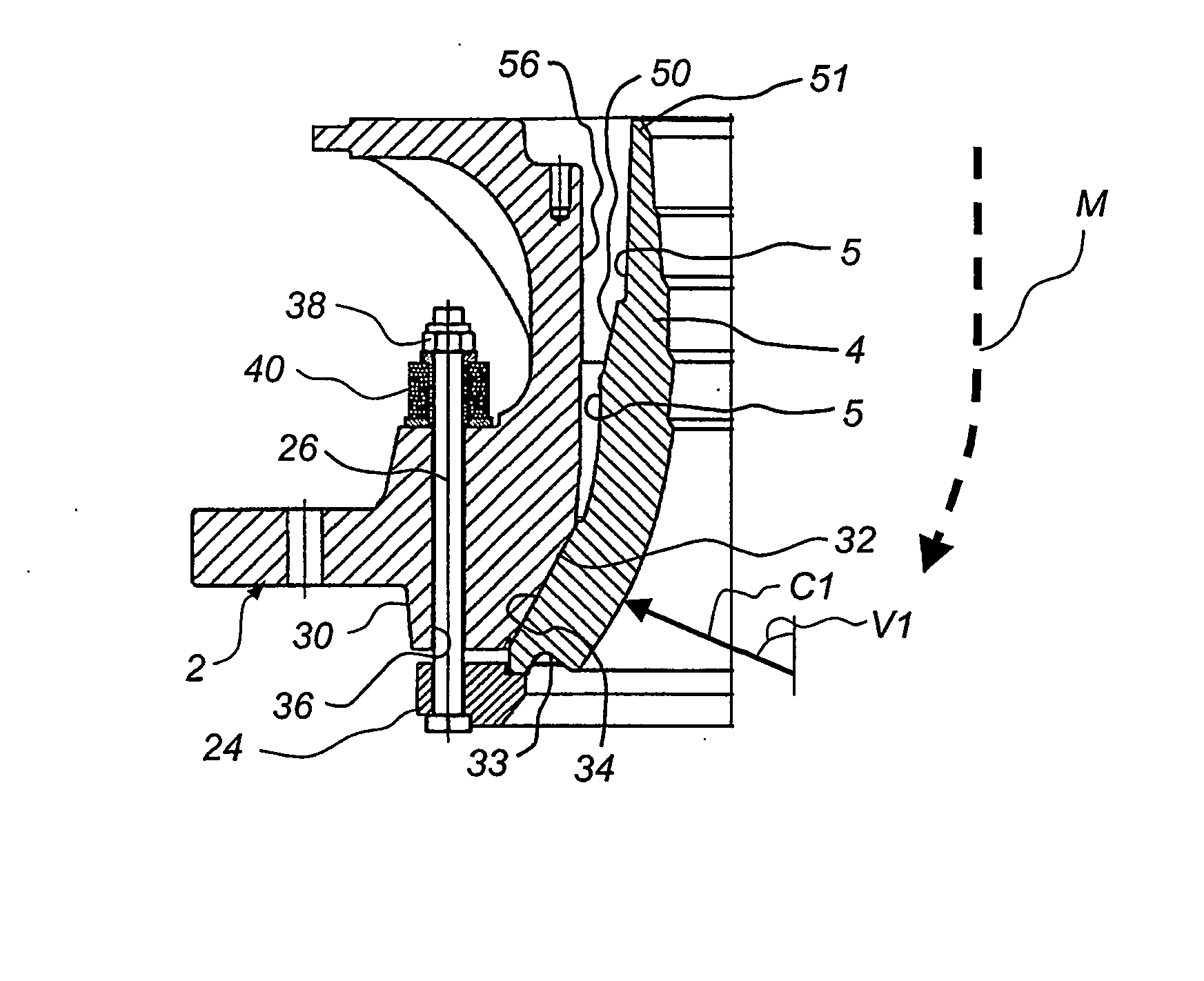
[0009] This object is attained by a method to fasten an outer shell in a gyratory crusher, which method is characterized in that in a first step a first abutment surface on the outer periphery of the outer shell is brought to abutment against a first contact surface on the frame, and that in a second step a spacer member for clamping of the outer shell is pressed in between a second abutment surface on the outer periphery of the outer shell and the frame. This method has the advantage that a very stable fixing of the outer shell is provided. The two abutment surfaces have the advantage that relatively limited portions of the outer shell have to be machined to accurate tolerances. The first and the second abutment surface may be machined to different angles to the vertical plane, which gives a possibility of choosing angles that are optimal for the position in question on the periphery of the outer shell. The fact that the fixing is made in two steps makes it easier to provide a good abutment both at the first and the second abutment surface. In particular, the invention has the advantage that it becomes simple to provide a good metallic abutment at both the first and the second abutment surface. A metallic abutment is mechanically stable and is also preferred from a working environment point of view.
[0010] Preferably said abutment surface is located at the lower end of the outer shell seen in a material flow direction, said second abutment surface being situated closer to the upper end of the outer shell seen in the material flow direction. The greatest crushing forces usually arise at the end of the crushing, i.e., in the lower end of the outer shell seen in the material flow direction. The first abutment surface gets in this way a very stable abutment and can in the best way withstand the crushing forces in the lower portion of the crusher.

Problems solved by technology

The locking devices disclosed in U.S. Pat. No. 6,007,009 are, however, mechanically complicated and involve a mechanically seen weak fixing of the outer shell.

Method used


Image

  • Method and Device for Clamping of Crushing Shell
  • Method and Device for Clamping of Crushing Shell
  • Method and Device for Clamping of Crushing Shell

Examples


Embodiment Construction

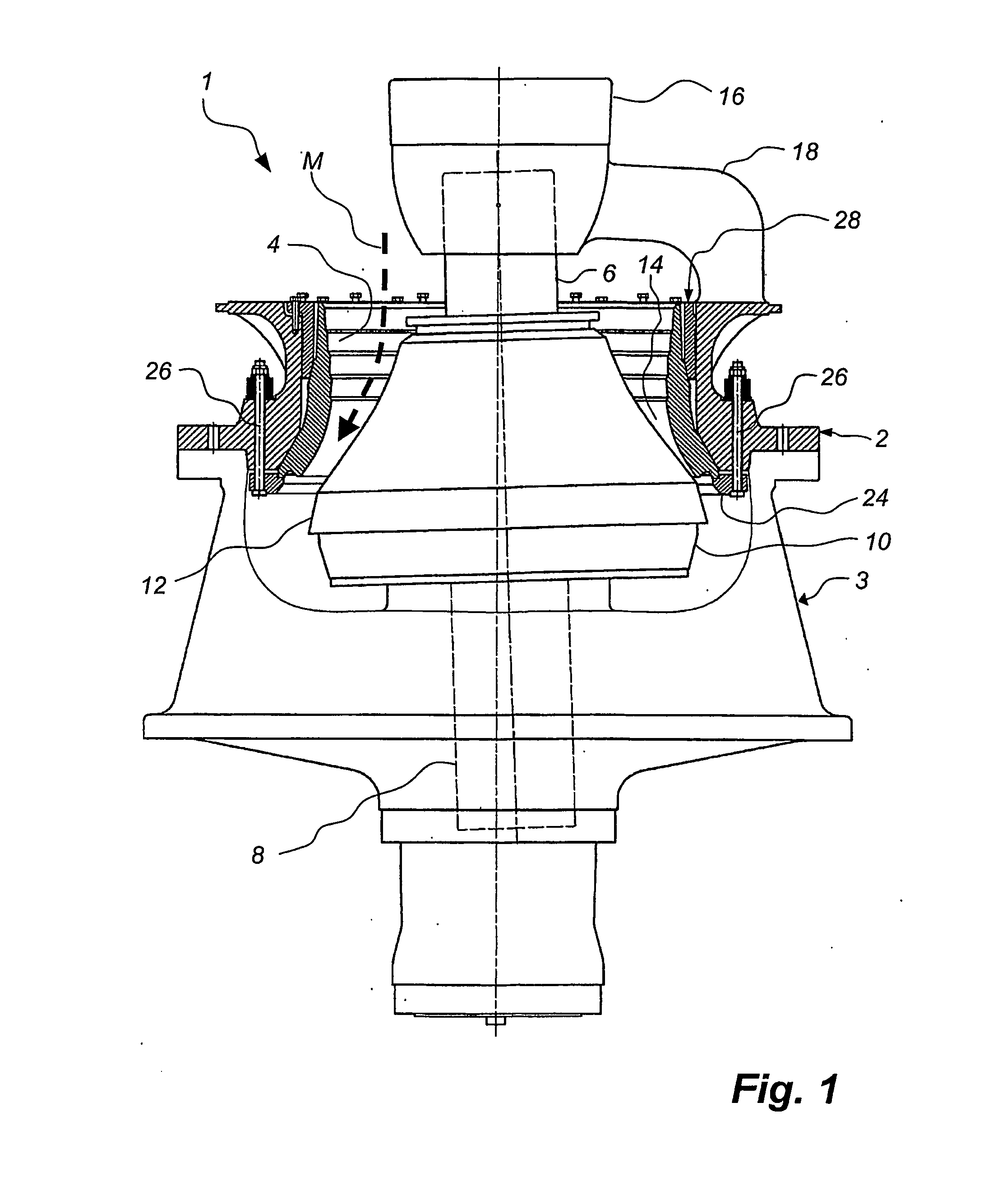
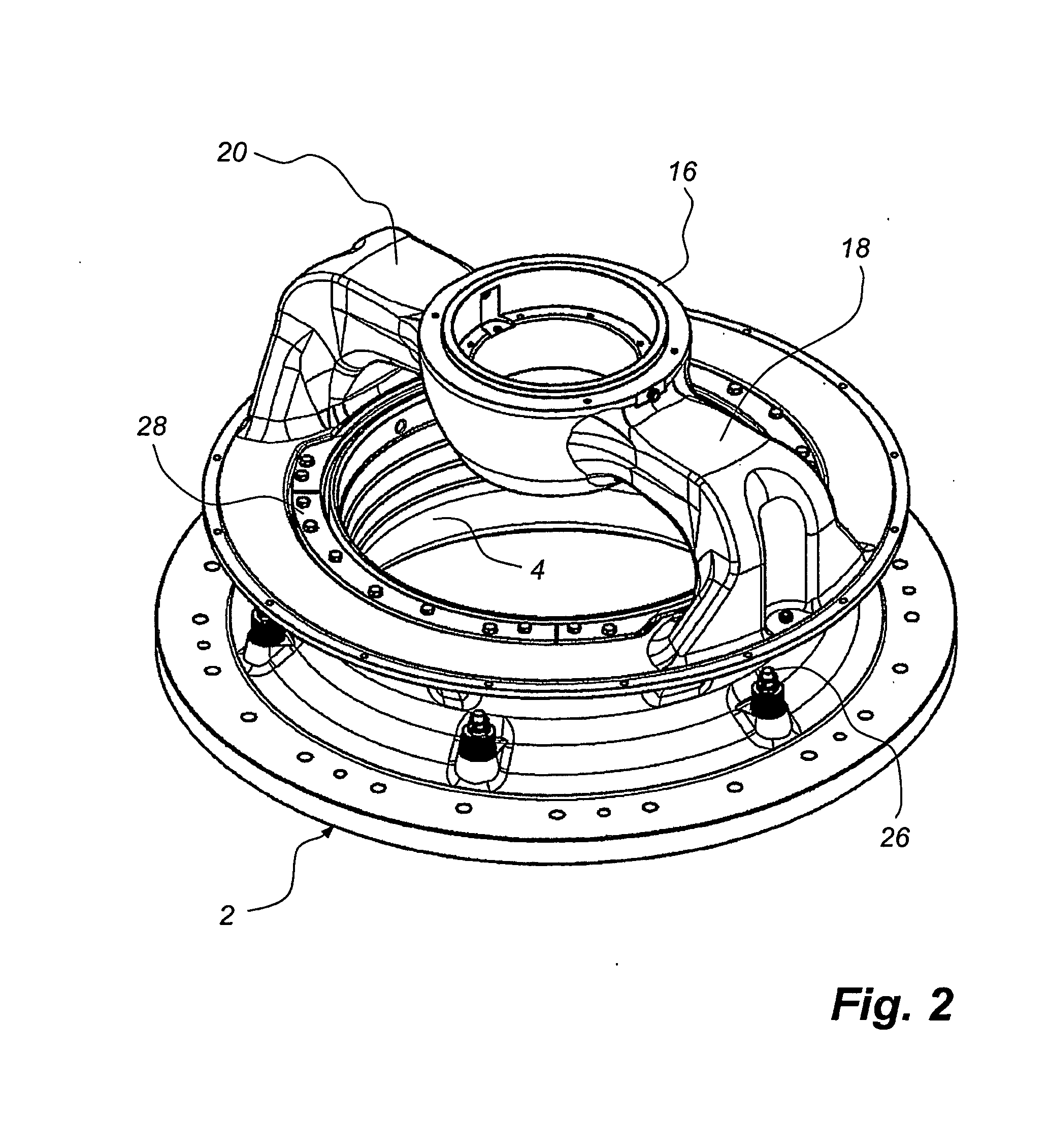
[0047] In FIG. 1, a gyratory crusher 1 is shown schematically, which has a frame in the form of an upper part 2, which is detachably attached on a bottom part 3. In the upper part 2, a crushing shell in the form of an outer shell 4 is attached. The outer shell 4 is of a type, which is utilized in crushing of relatively rough material. The gyratory crusher 1 has also a shaft 6. At the lower end 8 thereof, the shaft 6 is eccentrically mounted in the bottom part 3. At the upper end thereof, the shaft 6 carries a crushing head 10. A second crushing shell in the form of an inner shell 12 is mounted on the outside of the crushing head 10. The outer shell 4 surrounds the inner shell 12 in such a way that between said shells 4, 12, a crushing gap 14 is formed, which in axial section, such as is shown in FIG. 1, has in direction downwardly decreasing width. The shaft 6, and thereby the crushing head 10 and the inner shell 12, is vertically movable by means of a hydraulic adjusting device, no...


PUM

PropertyMeasurementUnit
angleaaaaaaaaaa
angleaaaaaaaaaa
angleaaaaaaaaaa

Abstract

A gyratory crusher comprises an outer shell, which should be fastened in a frame included in the crusher, and an inner shell, which is intended to be fastened on a crushing head and to define together with the outer shell a crushing gap for receipt of material to be crushed. Upon fastening of the outer shell a first abutment surface on the outer periphery of the outer shell is brought in a first step to abutment against a first contact surface on the frame. In a second step a spacer member is pressed in for clamping of the outer shell between a second surface on the outer periphery of the outer shell and the frame. A good abutment is provided both at the first abutment. Surface of the outer shell and at the second abutment surface thereof.

Description

TECHNICAL AREA [0001] The present invention relates to a method to fasten an outer shell in a gyratory crusher, which comprises the outer shell, which is to be fastened in a frame included in the crusher, and an inner shell, which is intended to be fastened on a crushing head and together with the outer shell define a crushing gap for receipt of material which is to be crushed. [0002] The present invention also relates to an outer shell for fixing in a gyratory crusher. [0003] The invention also relates to a gyratory crusher, which is of the above-mentioned kind and in which an outer shell can be fixed. [0004] The invention also relates to a spacer member for use in the fixing of an outer shell in a gyratory crusher. TECHNICAL BACKGROUND [0005] A gyratory crusher, which is of the above-mentioned kind, can be utilized for crushing hard objects, for instance blocks of stone. During the crushing, the shells of the crusher are worn and these therefore have to be exchanged at regular int...

Claims


Application Information

Patent Timeline
Patent Type & Authority Applications(United States)
IPC IPC(8): B02C2/00B23P19/04B02CB02C2/06
CPCY10T29/53B02C2/005
Inventor OLSSON, GERT-AKESILFVER, ROLFWULFF, TORBJORN NILSSON
Owner SANDVIK INTELLECTUAL PROPERTY AB
Learn More