
Assessment Apparatus and Method

Inactive Publication Date: 2007-11-29
QUEENSLAND THE UNIV OF
View PDF3 Cites 8 Cited by
  • Summary
  • Abstract
  • Description
  • Claims
  • Application Information

AI Technical Summary

Benefits of technology

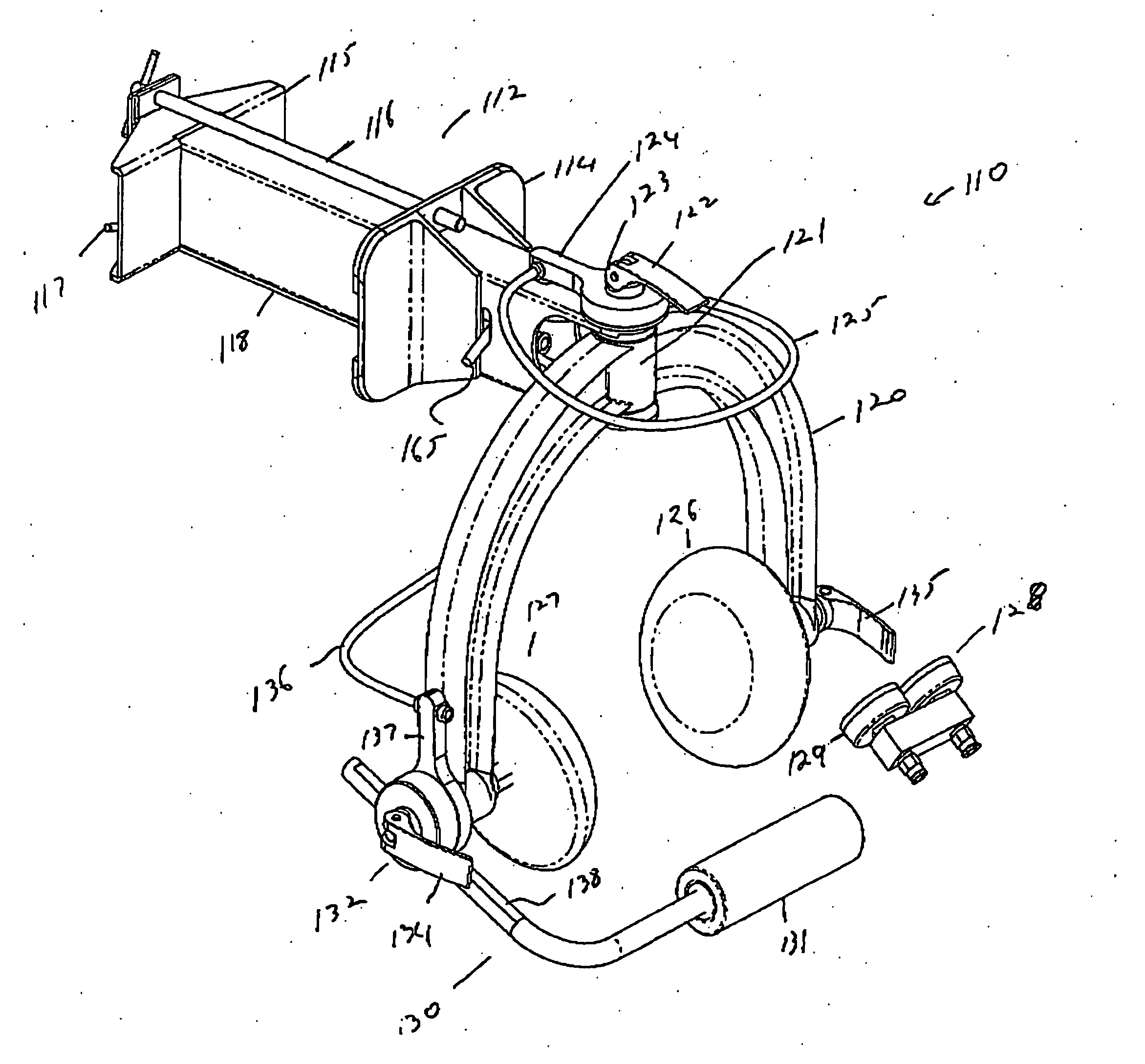
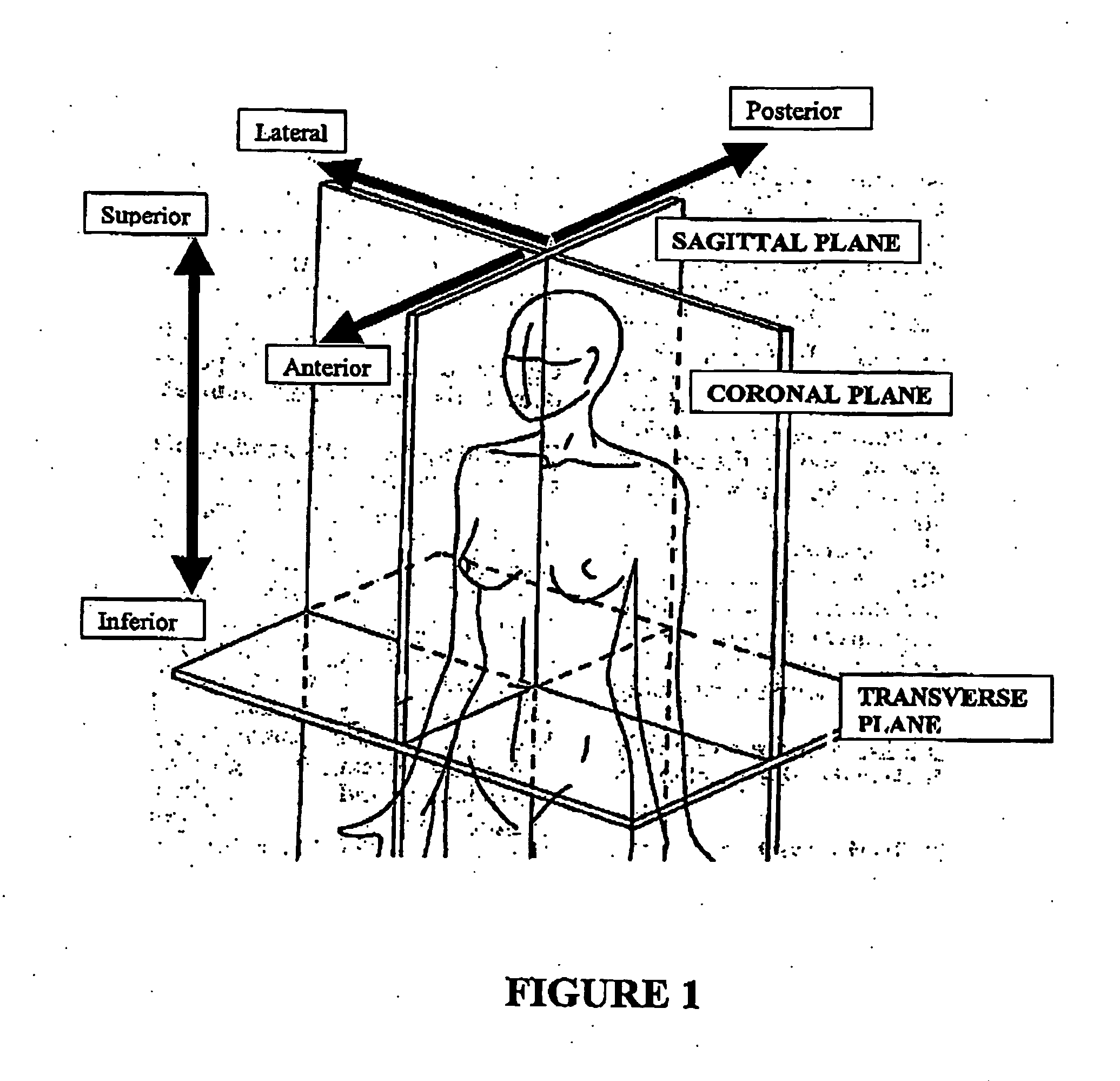
[0040] The apparatus may further comprise display means for providing feedback to a subject. The display means may be an audible signal and / or a visual signal such as a visual display unit. The visual display unit may be adjustable such that it can be positioned in full view of the patient or removed from the view of the patient if desired. The visual display unit can be programmed to display only parts or all of the test outcomes both during and following the completion of the test eg. Torque, head weight force, or other information used in the test such as electromyographic information as described below. The visual display means may comprise a pressure, force or torque gauge for also measuring pressure or force generated by a subject in performing an exercise, particularly an isometric exercise. The gauge may be a hydraulic gauge having an input line co-operatively coupled to a corresponding piston arrangement, wherein the line may be in fluid connection with the gauge when the corresponding piston arrangement is locked to thereby prevent movement of the piston and lever arm and provide an isometric application for the subject. The apparatus may comprise two gauges, each connected to a corresponding piston arrangement which may be for flexion / extension in the sagittal plane and rotation in the transverse plane, respectively. The gauges may provide an indication of isometrically provided force. In an alternative embodiment, the gauges may be electronic gauges as are well known. The gauges may be in signal connection with a display such as an LED display and also with processing means such as a computer for recording and / or analysis of the results.

Problems solved by technology

There is however no direct method to measure the performance of these muscles, which hampers scrutiny of their involvement in neck pain and limits the clinical implementation and assessment of a structured exercise program.

Method used


Image

  • Assessment Apparatus and Method
  • Assessment Apparatus and Method
  • Assessment Apparatus and Method

Examples


example 2

[0181] This method was directed to AOR specific to primary articulations. This method used known bony anatomical landmarks that are representative of the AOR for motion of the articulations primarily targeted during C-C motion. For example the primary C-C articulation of C-C flexion and extension is the C0 / 1 (atlanto-occipital) motion segment. The radiographic located AOR for C0 / 1 flexion / extension occurs about a point slightly superior and anterior to the mastoid process of the skull (FIG. 5,8) [29-31] perpendicular to the sagittal plane. Torque measured about this AOR would represent the torque of the CC flexor or extensor muscles about the primary AOR of C-C flexion and extension. For C-C axial rotation the axis of rotation is near the vertex of the head perpendicular to the transverse plane and in line with the axis of rotation of the C1 / 2 (atlanto-axial articulation) articulation (FIG. 12), the principle articulation for C-C axial rotation. It is acknowledged that these motions...

example 3

Isometric Maximal Voluntary Contraction Muscle Test

[0213] The patient and C-CD are positioned corresponding to the patients AOR and in the predetermined C-C range as described above. The patient is asked to ‘nod their head such that their jaw pushes down onto the padded bar so that the head remains in contact with the surface it rests on’. The patient is asked to perform C-C flexion gently at first to warm up. When the therapist is satisfied the test is performed correctly the patient is asked to repeat the test but this time to perform the action as hard as possible. The patient is given visual feedback (FIG. 25) through an overhead display 36 of the increase in torque with their increasing effort. The visual feedback is displayed as an elevating mark on a graph. A rest period is given between trials. FIG. 20 is an example of the output for this test. A test-retest study has been performed to assess the reliability of C-C dynamometry in the measurement of C-C flexor muscle perform...

example 4

Isometric Endurance

[0214] A predetermined percentage (eg. 20 or 50%) of the person's maximal voluntary contraction or an arbitrary torque intensity is chosen. A visual display gives the patient the torque intensity level required. The participant is asked to ‘nod their head such that their jaw pushes down onto the padded bar to achieve the pre-determined torque intensity and is asked to maintain this torque intensity as accurately as possible for a predetermined time period or until the torque level decays beyond a certain level (eg. 50% of the pre-determined level). This may also be called a sustained voluntary contraction (SVC). FIG. 21 is an example of the recorded output from this test. Variations of these tests can be performed so that the patient may be asked to control the torque output only, or both torque and head weight force simultaneously.

[0215] The mechanical components of a preferred embodiment of the apparatus of the present invention are shown in FIGS. 26 and 27. T...


PUM


Abstract

A method and apparatus are described for assessing function of the cranio-cervical muscles. The method includes assessment of torque produced during flexion / extension, axial rotation, lateral rotation or combination thereof. The apparatus (110) has a lever arm (130) mounted to a support frame (120), wherein the length of the arm and its angle of extension may be varied. Torque is assessed at an anatomical axis of rotation in a subject. The apparatus axis of rotation may be adjustable. A preferred embodiment has a pivoted support frame for positioning over a subject's head, wherein the support frame (120) may form a lever arm for rotation. The apparatus may be removably mountable to an upright such as a door jamb.

Description

FIELD OF THE INVENTION [0001] THIS INVENTION relates to a device and method for assessing the performance of a muscle or muscles in a subject. More particularly, the invention relates to a device and method for assessing the cranio-cervical muscles of a subject but is not limited to this group and may be applied to other muscles and / or muscle groups. BACKGROUND OF THE INVENTION [0002] Neck pain affects 13-20% of the population [1, 2] and approximately 70% of all people will experience neck pain at some point in their life [2, 3]. Traumatic neck injury such as whiplash, is the most commonly reported injury in some jurisdictions. In addition 16% of the population has a headache at any one time [5] and 14-18% of these headaches originate from the neck (cervicogenic headache) [6, 7]. Neck pain and back pain are the most common reasons for visits to a physiotherapist (42% of visits) [8]. In recent years substantial evidence has emerged identifying impairment in the muscle system which in...

Claims


Application Information

Patent Timeline
IPC IPC(8): A61B5/22A63B23/025
CPCA61B5/224A61B5/4519A63B23/025A61B5/6814A61B5/4528
Inventor O'LEARY, SHAUN PATRICKJULL, GWENDDEN ANNEVICENZINO, GUGLISIMO TARCISIOGREAVES, MATTHEW CAMPBELL
Owner QUEENSLAND THE UNIV OF
Learn More