
Method And Apparatus For Drying Under Reduced Pressure Using Microwaves

a technology of microwaves and drying methods, applied in the direction of drying machines with progressive movements, meat/fish preservation by irradiation/electric treatment, etc., can solve the problems of poor yield, increase in personnel costs, decomposition of vitamins and the like,

Inactive Publication Date: 2007-11-29
KITAKYUSHU FOUND FOR THE ADVANCEMENT OF IND +1
View PDF74 Cites 40 Cited by
  • Summary
  • Abstract
  • Description
  • Claims
  • Application Information

AI Technical Summary

Benefits of technology

[0005] The present invention has been made to overcome the above disadvantages of the prior arts and aims to provide a method and an apparatus for drying an object under reduced pressure using microwaves, operable to dry the object in a short period of time at low temperatures at which the object does not deteriorate.

Problems solved by technology

However, in the case of sun-drying the foodstuffs, there have been problems of poor yields due to generation of mold and an increase in personnel costs.
Moreover, drying the vegetables at high temperatures causes decompositions of vitamins and the like.
Consequently, much heat is applied to the object, causing the object to be deteriorated or even burned in some cases.
However, protein and starch are deteriorated by heating even at relatively low temperatures, resulting in changes in constituents of the food.
When drying laundry with microwaves, the temperature thereof becomes excessively high, thereby damaging cloth of the laundry or causing the laundry to shrink.
When drying lumber using microwaves, inner cellulose is deteriorated, which may hinder the natural properties of the lumber.
Moreover, when drying electrical equipment by heating, elements and materials thereof are deteriorated or deformed depending on the heating temperature, which may result in damage of the equipment itself.

Method used


Image

  • Method And Apparatus For Drying Under Reduced Pressure Using Microwaves
  • Method And Apparatus For Drying Under Reduced Pressure Using Microwaves
  • Method And Apparatus For Drying Under Reduced Pressure Using Microwaves

Examples


empirical example 1

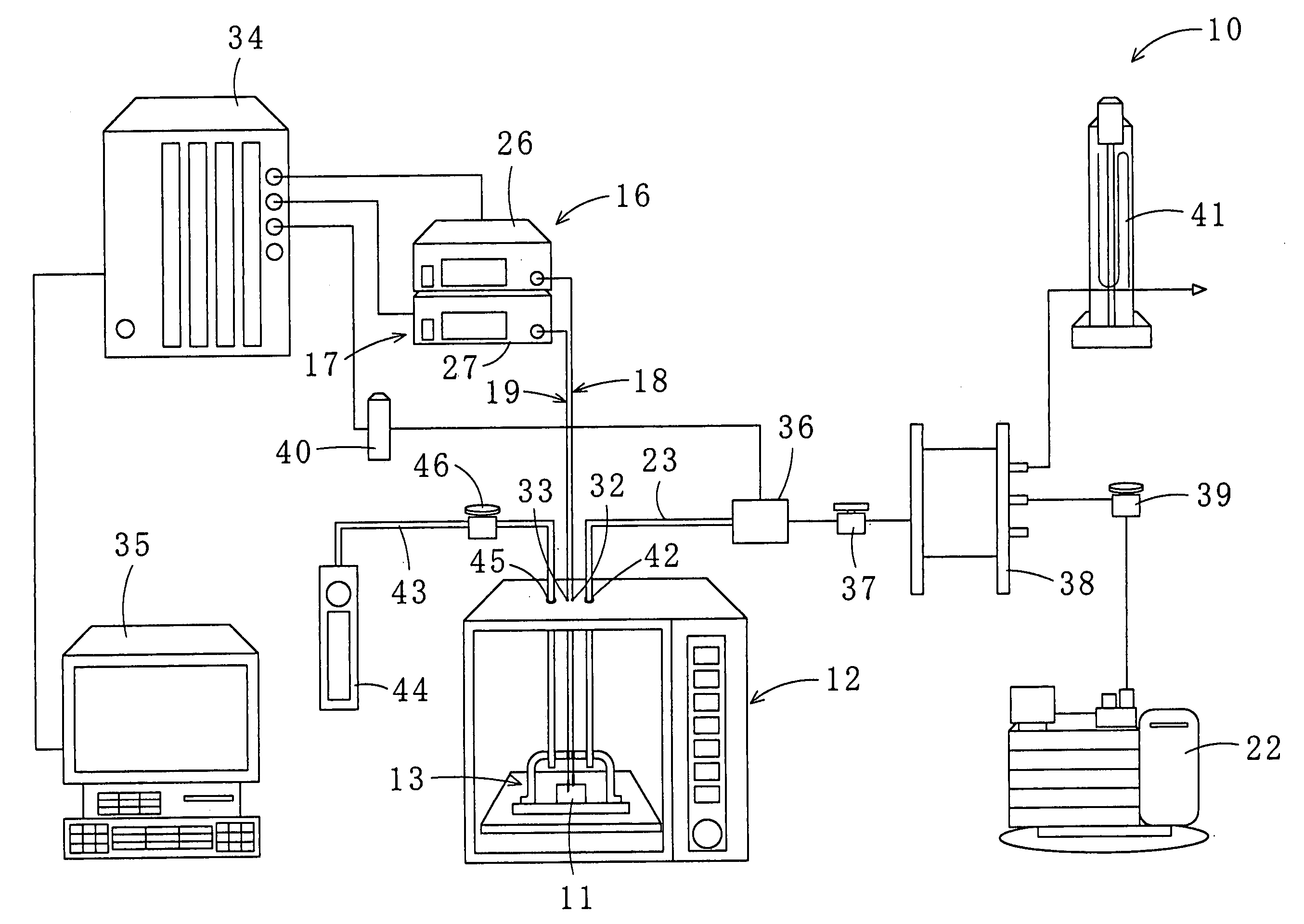
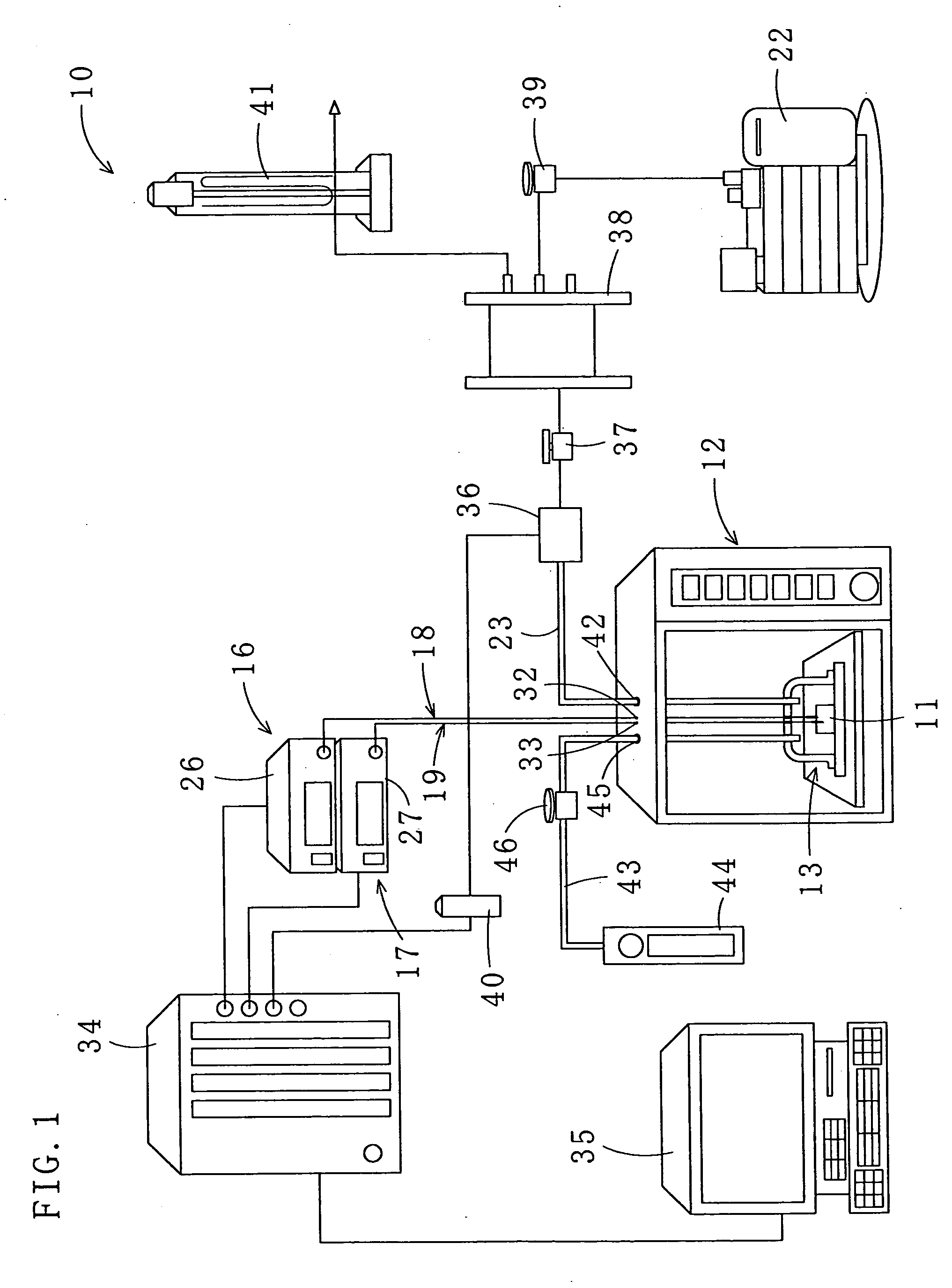
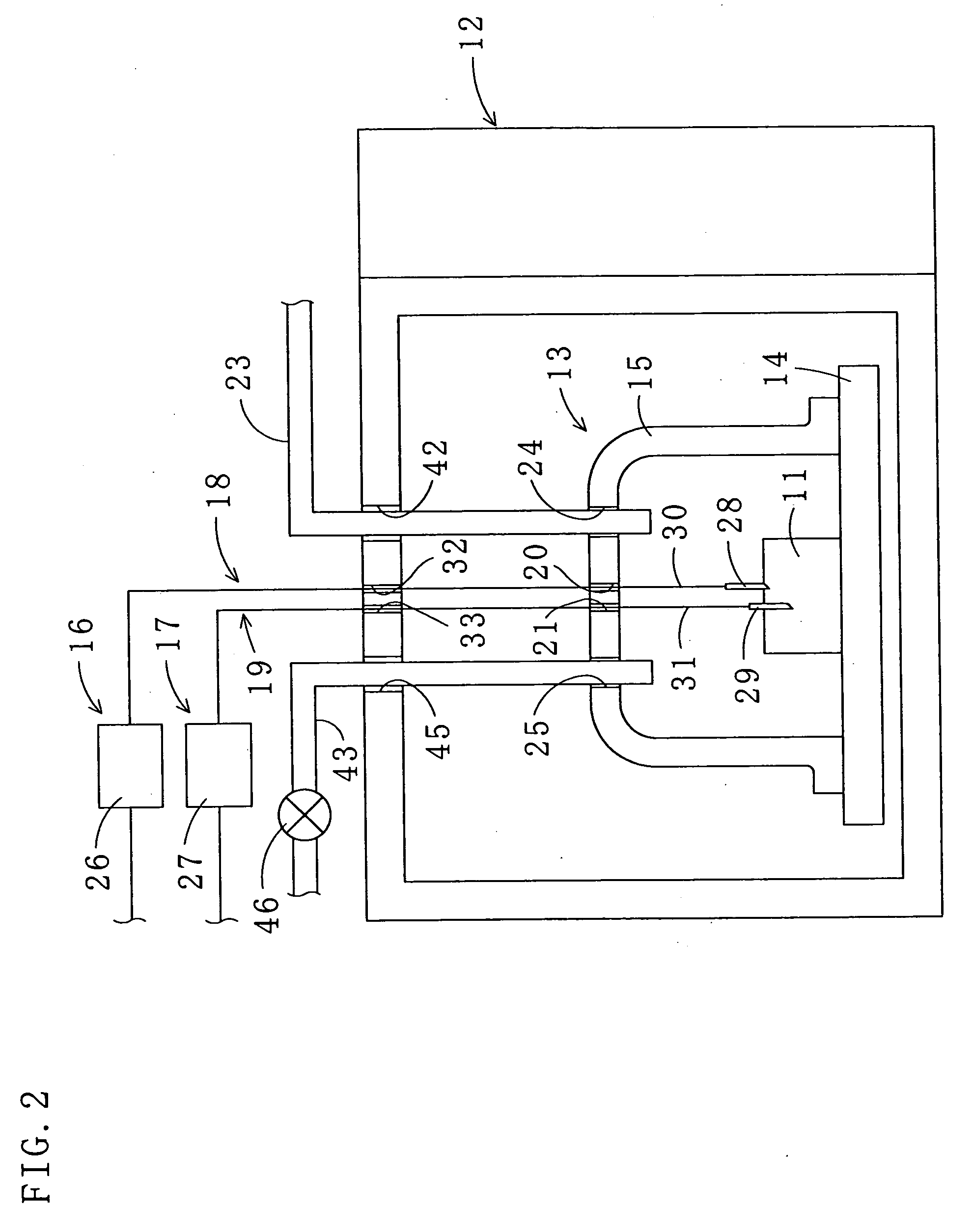
[0099] The objects 11, the scallop adductor muscles, were dried by microwave irradiation using the apparatus 10 to which the method for drying under reduced pressure according to the first embodiment is applied. The flow-regulating valve 46 of the apparatus 10 was closed, and the open / close valve 37 and the pressure-regulating valve 39 were opened. The inside of the chamber 13 was depressurized to 50, 100 and 150 mmHg by the depressurizing pump 22. The specific temperatures “A” and “B” were set to 40° C. and 30° C., respectively. The objects 11 were heated and dried in the pulsing manner at respective pressures, and the moisture contents thereof were measured at predetermined times. The moisture content is a value calculated by dividing weight (g) of the water in the object by weight (g-dry) of the thoroughly dried object (the same is true in the following examples). As shown in FIG. 13, the lower the pressure in the chamber 13 was (50 mmHg), the larger the water reducing rate of th...

empirical example 2

[0100] The objects 11, the scallop adductor muscles, were dried by microwave irradiation using the apparatus 10. The flow-regulating valve 46 of the apparatus 10 was opened, and the open / close valve 37 and the pressure-regulating valve 39 were opened. The inside of the chamber 13 was depressurized to 50 mmHg by the depressurizing pump 22. Flow rates of the air (an example of the gas) supplied into the chamber 13 were set to 0, 1.0, 1.5, 2.0, 2.5, and 3.0 L / min., and the specific temperatures “A” and “B” were set to 40° C. and 30° C., respectively. The objects 11 were heated and dried in the pulsing manner at respective air flow rates, and the moisture contents thereof were measured at predetermined times. The moisture content at the air flow rate of 0 L / min is the same as that in the Empirical Example 1. As shown in FIG. 14, the air supply into the chamber 13 improved drying efficiency. Furthermore, drying with the air supplied into the chamber 13 at the flow rates of 1.0 and 1.5 L / ...

empirical example 3

[0101] The object 11, the scallop adductor muscle, was dried by microwave irradiation using the apparatus 10. The flow-regulating valve 46 of the apparatus 10 was opened, and the open / close valve 37 and the pressure-regulating valve 39 were opened. The inside of the chamber 13 was depressurized to 50 mmHg by the depressurizing pump 22. The flow rate of the air supplied into the chamber 13 was set to 1.0 L / min, and the object 11 was heated and dried in the pulsing manner (same as in the case of air flow rate of 1.0 L / min in the Empirical Example 2). As a comparative example, the object was dried under the same conditions except that the microwaves were irradiated continuously, and the moisture content of the object was measured at predetermined times. As shown in FIG. 15, when the microwaves were irradiated continuously, the drying time was longer and more electric power was used compared with the case where the microwaves were irradiated in the pulsing manner. Furthermore, because o...


PUM


Abstract

An apparatus and a method for drying under reduced pressure using microwaves. The apparatus comprises a chamber (13) for housing an object (11), a depressurizing pump (22) connected to the chamber (13) for depressurizing the inside of the chamber (13), a microwave irradiating device (12) for irradiating microwaves to the object (11) in the chamber (13), an airflow generating device for generating an airflow in the chamber (13) by introducing a gas from the outside to the inside of the chamber (13), and a control device (35) for controlling the above components. The object (11) in the chamber (13) is dried at temperatures below a deterioration temperature of the object (11) by intermittent irradiation of the microwaves under reduced pressure while the airflow is generated around the object (11).

Description

TECHNICAL FIELD [0001] The present invention relates to a method and an apparatus for reduced pressure drying an object which is deteriorated depending on temperature using microwave irradiation. The deterioration of the object means substantial change in its constituents, deformation, etc. BACKGROUND ART [0002] Foodstuffs such as scallop adductor muscles and abalones are conventionally dried by being exposed to the sun for about three months. Dried vegetables used in health foods and instant foods are produced by crushing raw vegetables and then drying the vegetable pieces alone or the vegetable pieces mixed with water in a temperature range of 100 to 200° C. Japanese Patent Application Publication No. 7-208862 discloses a vacuum electromagnetic heating dryer. According to the invention disclosed in the publication, an article to be dried (an object) is placed in a pressure-resistant container, the inside of the pressure-resistant container is depressurized, and microwaves are irra...

Claims


Application Information

Patent Timeline
IPC IPC(8): F26B3/34A23B4/015A23B4/03A23B7/015A23L3/40A23L3/54A23L17/00A23L17/40F26B3/347F26B5/04F26B15/14
CPCA23B4/015A23B4/03A23B7/015A23L3/54F26B15/14F26B5/048F26B11/02F26B15/04F26B3/343F26B3/347F26B5/04A23L3/40A23L17/00
Inventor TSURUTA, TAKAHARUHAYASHI, TADAHISA
Owner KITAKYUSHU FOUND FOR THE ADVANCEMENT OF IND
Learn More