
Engine intake air compressor having multiple inlets and method

a technology of intake air compressor and compressor, which is applied in the direction of machines/engines, liquid fuel engines, mechanical equipment, etc., can solve the problems of insufficiently meeting the requirements of modern engine systems and the improvement of the flow capacity of compressors, and achieves the improvement of the performance of the engine intake air compressor, the effect of reducing the number of inlet holes

Active Publication Date: 2007-11-22
INT ENGINE INTPROP CO LLC
View PDF11 Cites 38 Cited by
  • Summary
  • Abstract
  • Description
  • Claims
  • Application Information

AI Technical Summary

Benefits of technology

The invention is an engine intake air compressor with improved flow range capability. It includes a compressor housing with a main inlet annular cavity and a secondary inlet passage. The secondary inlet passage has an aerodynamic profile and is positioned around the main inlet bore. The compressor wheel has vanes with a stepped portion forming an enlarged inducer portion located adjacent to the inducer slot of the secondary inlet passage. The inducer slot can connect with multiple inducer slots or an exterior inlet source. The method of manufacturing the compressor includes casting the housing with the secondary inlet passage and machining the inducer bore and inducer slot. The compressor wheel is attached to a shaft and the housing is assembled around the compressor wheel. The method also includes connecting the compressor wheel to a shaft and positioning the inducer slot in the secondary inlet passage. The invention allows for improved performance under near choke conditions by providing an enlarged effective flow diameter and greater air flow capacity of the compressor. It also allows for the improvement of performance under surge conditions by admitting a portion of the air flow from the turbulence field generated by the outer edges of the vanes into the secondary inlet passage through the inducer opening for mixing with the intake air to the compressor upstream of the entrance point to the inducer bore because the flow of air in the secondary inlet passage will be in the reverse direction under these conditions.

Problems solved by technology

One main disadvantage of the Fisher configuration for a recirculation system is that the improvements to the flow capability of the compressor are limited and are inadequate in meeting the requirements of modern engine systems.

Method used


Image

  • Engine intake air compressor having multiple inlets and method
  • Engine intake air compressor having multiple inlets and method
  • Engine intake air compressor having multiple inlets and method

Examples


Embodiment Construction

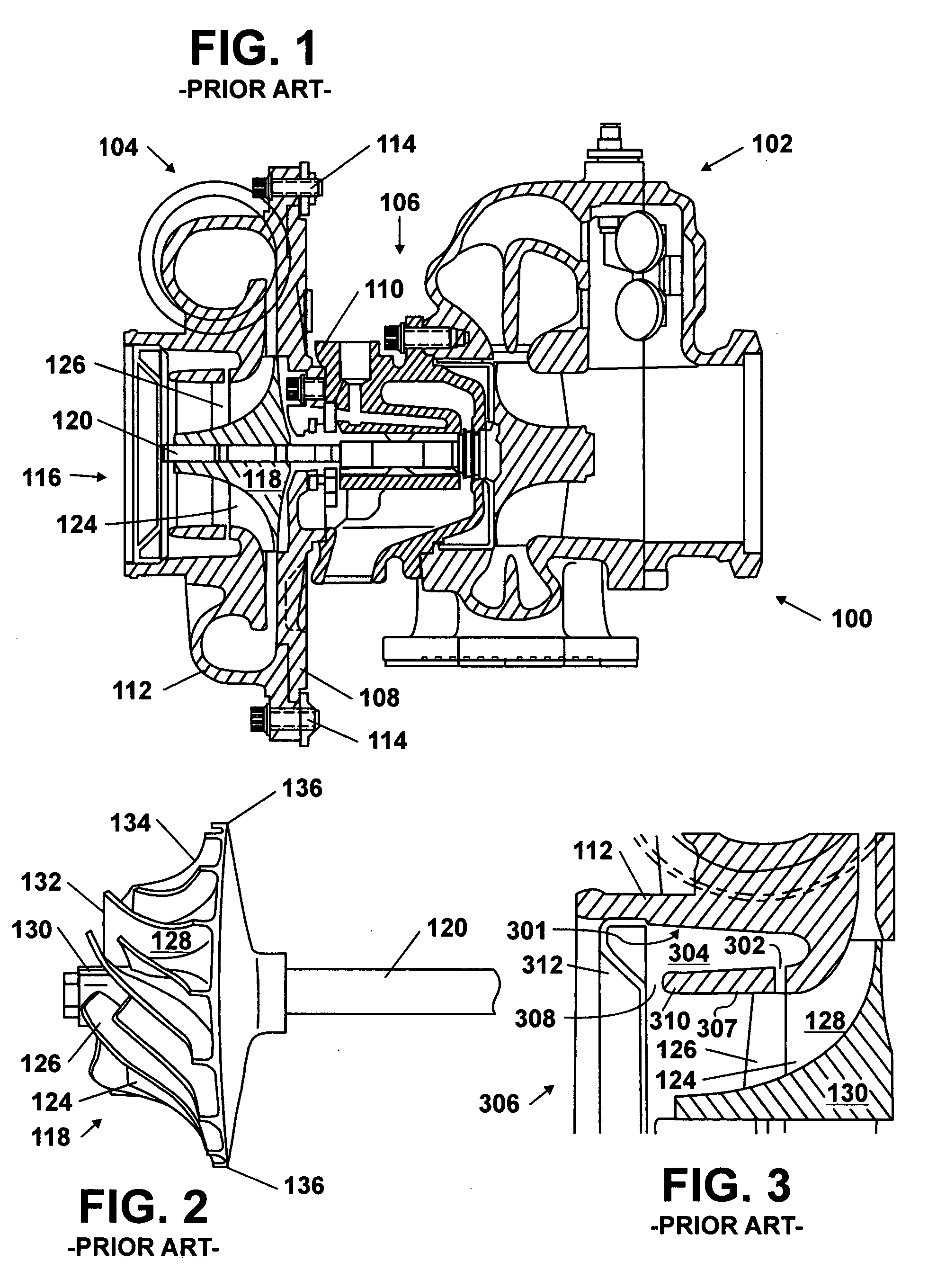
[0025]The following describes an apparatus for and method of extending the flow range of a compressor for use with an internal combustion engine. Although the invention is applicable to a mechanically-driven supercharger, this description is in the context of an exhaust-gas-driven turbocharger. As shown in FIG. 1, the turbocharger 100 includes a turbine assembly 102 connected to a compressor assembly 104 through a center-housing assembly 106. The compressor assembly 104 includes a back-plate 108 that is connected to a casting 110 of the center-housing 106. The back-plate 108 is connected to a compressor housing 112 and secured with a plurality of bolts 114. Other compressors may use v-band clamps, bone-clamps, or other connection configurations. The compressor housing for a typical compressor may be made of aluminum, and may be formed by a die-casting operation, although other materials and manufacturing methods can and have been used in the past.

[0026]The compressor assembly 104 ha...


PUM


Abstract

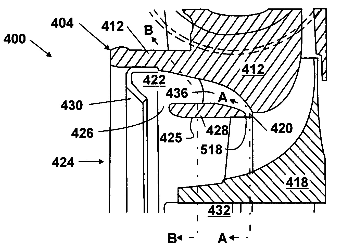
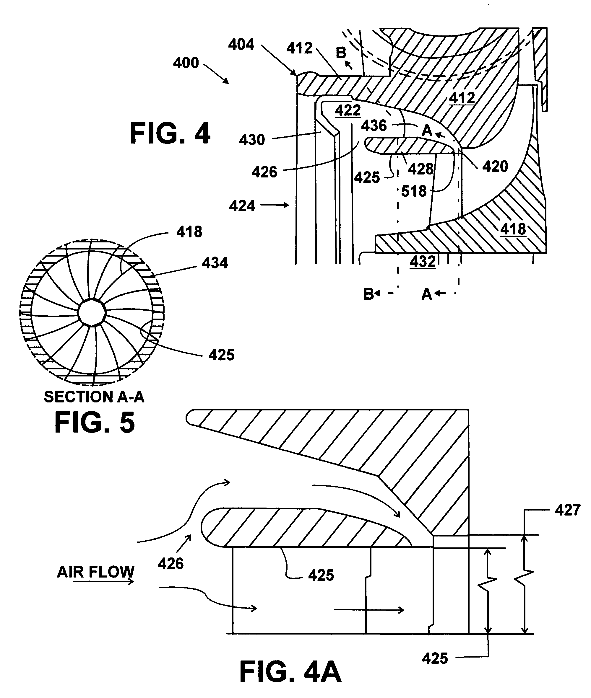
A compressor assembly (404) includes a compressor housing (412) having a main inlet bore (424) and a secondary inlet passage (422) that has an increasing flow cross-sectional area. The secondary inlet passage (422) is positioned in the compressor housing (412) and around the main inlet bore (424). A secondary inlet slot (426) and an outlet slot (420) fluidly connect the secondary inlet passage (422) with the main inlet bore (424). A compressor wheel (418) is in the compressor housing (412) and has a stepped portion (518) formed by at least one plurality of vanes (506). The stepped portion (518) is located adjacent to the outlet slot (420) of the housing (412).

Description

FIELD OF THE INVENTION [0001]This invention relates to intake air compressors, such as turbochargers or superchargers, for internal combustion engines.BACKGROUND OF THE INVENTION [0002]Engines having compressors for intake air, such as turbochargers or superchargers are well known. Compressor efficiency over a large range of operation is desired for economical and efficient operation of the engine. All compressors are limited by a “surge” condition and a “choke” condition. Compressor surging occurs at high pressure ratios and low airflows for a given rotational speed of a compressor wheel, and is shown as a surge line on a compressor map. When surging occurs, the compressor begins operating in a region of diminishing returns and more power input is required to continue operating the compressor while the compressor progressively provides less air at a lower pressure. Compressor choking occurs at higher air flow conditions for a given rotational speed. Compressor choking represents th...

Claims


Application Information

Patent Timeline
Patent Type & Authority Applications(United States)
IPC IPC(8): F01D1/12
CPCF02C6/12F04D29/441F04D29/4213F04D29/685F05D2250/51Y10S415/914
Inventor WOOD, TERRY G.
Owner INT ENGINE INTPROP CO LLC
Learn More