
Method of forming a structural component having a NANO sized/sub-micron homogeneous grain structure

a technology of nano-sized/sub-micron grain structure and structural component, which is applied in the field of manufacturing process of structural components, can solve the problems of complex die structure and components, high cost of construction using such billets, and known dies having a detrimental operation, so as to reduce friction between workpieces

Inactive Publication Date: 2007-11-15
GENERAL ELECTRIC CO
View PDF10 Cites 15 Cited by
  • Summary
  • Abstract
  • Description
  • Claims
  • Application Information

AI Technical Summary

Benefits of technology

[0014] According to yet another aspect of the present disclosure, the method has the first sacrificial material surrounding the work piece in a manner to reduce friction between the work piece during extrusion. The method also has the step of optionally repeating extrusion of the first sacrificial material and the work piece through the die.

Problems solved by technology

However, construction using such billets is expensive, due in part, because the billets or desired structural components can be formed only by using a very complex and cumbersome die structure.
The complex die structure and components are expensive to use and make.
Moreover, such known dies have a detrimental operation and have die components that only minimize friction in one general direction or on the face of the work piece material.
Such a reduction in friction may only provide a limited structural enhancement depending on the application.
This results in non-homogenous sized grains in the resulting structural component.
This non-homogenous condition due to the increased friction on the one side relates to poor mechanical properties.
This may lead to one or more unintended detriments depending on the structural application.

Method used


Image

  • Method of forming a structural component having a NANO sized/sub-micron homogeneous grain structure
  • Method of forming a structural component having a NANO sized/sub-micron homogeneous grain structure
  • Method of forming a structural component having a NANO sized/sub-micron homogeneous grain structure

Examples


Embodiment Construction

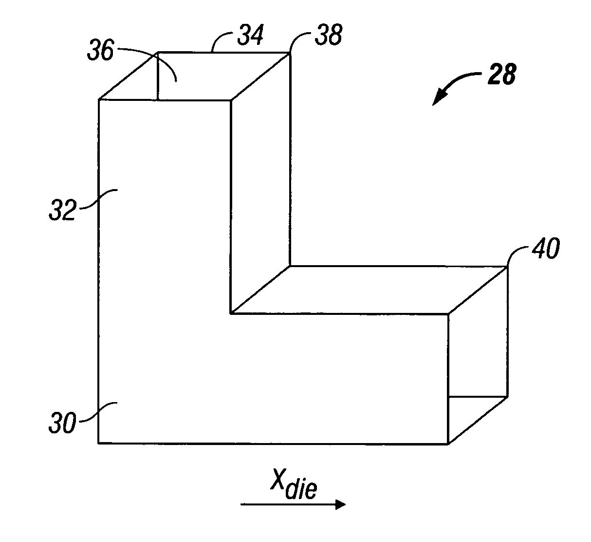
[0039] Reference should be made to the drawings where like reference numerals refer to similar elements throughout the various figures. The fabrication process of the present disclosure controls a microstructure of a work piece material resulting from a deformation of the work piece material. The fabrication process uses a first sacrificial material and, in some embodiments, a second sacrificial material, to reduce friction between a die and the work piece, and thus form a homogenous nano / sub micron sized grains in the work piece material or work piece.

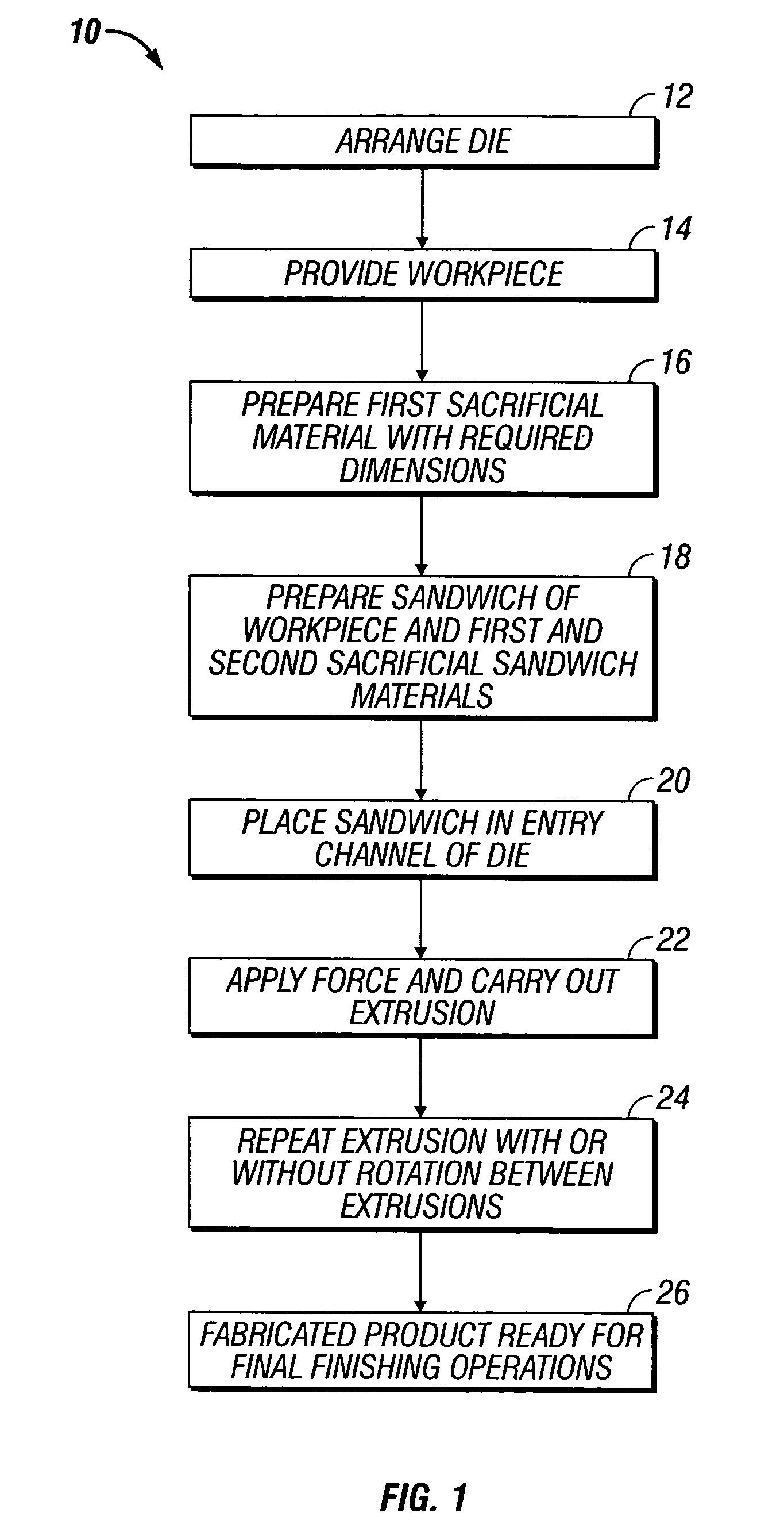
[0040] Referring now to FIG. 1, there is shown a process flow chart of the fabrication method 10 of the present disclosure. The method 10 has the first step 12 of arranging the die. Thereafter, the method proceeds to step 14. At step 14, the method has the step of providing a work piece in the die. The work piece is defined as the material that will undergo the plastic deformation in order to result in a controlled microstructure. Th...


PUM

PropertyMeasurementUnit
Angleaaaaaaaaaa
Structureaaaaaaaaaa
Sizeaaaaaaaaaa

Abstract

A method of making nano / sub-micron sized grains in a work piece material having a lateral side has the steps of providing a die. The die has an entrance channel with a longitudinal axis and an exit channel. The entrance channel and the exit channel are connected to one another to form an angle. The method has the step of providing a first sacrificial material with a complementary size to the work piece and placing the sacrificial first material and the work piece in an entrance channel. The first sacrificial material and the work piece are aligned with the longitudinal axis. The method has the step of extruding the combination of the first sacrificial material, and the work piece through the intersection of the entrance and the exit channels. The resulting shear deformation forms the nano / sub-micron sized grains in the work piece. This configuration reduces frictional effects thereby producing homogenous nano grain structure. This configuration reduces applied load and enables equal channel angular extrusion of thin sheets.

Description

BACKGROUND [0001] 1. Technical Field [0002] The present disclosure is directed to a fabrication process of a structural component. More particularly, the present disclosure is related to a fabrication process for a structural component to be used with high strength structural applications. Even more particularly, the present disclosure relates to a fabrication process for a structural component that results in a component having a homogeneous nano / sub-micron grain structure. [0003] 2. Description of the Related Art [0004] High strength engineering components are known in the art. Plastic deformation has been used in the art to structurally alter and to enhance one or more physical properties of a work piece component for different metallic materials. One such known method entails using a die having a movable surface in a deformation channel of the die. The movable surface moves with a work piece material during a deformation process in the deformation channel. The billets have selec...

Claims


Application Information

Patent Timeline
IPC IPC(8): B21C23/00
CPCB21C23/001B21C23/22B21C23/002
Inventor ORUGANTI, RAMKUMAR KASHYAPRAMANATHAN SUBRAMANIAN, PAZHAYANNURMARTE, JUDSON SLOAN
Owner GENERAL ELECTRIC CO
Learn More