
Adaptive maneuver based diagnostics for vehicle dynamics

a vehicle dynamics and adaptive maneuvering technology, applied in the field of vehicle stability control, can solve the problems of erroneous sensor output, more difficult to detect, and limited measurement range, and achieve the effect of increasing coverag

Inactive Publication Date: 2007-11-08
BWI CO LTD SA
View PDF8 Cites 39 Cited by
  • Summary
  • Abstract
  • Description
  • Claims
  • Application Information

AI Technical Summary

Benefits of technology

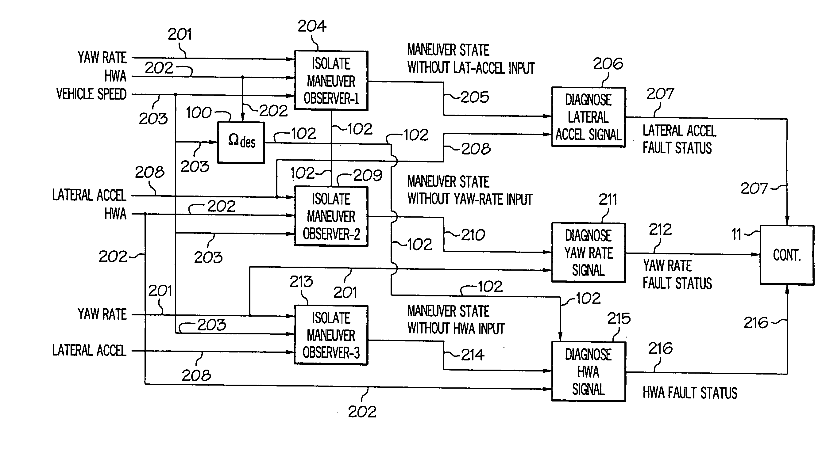
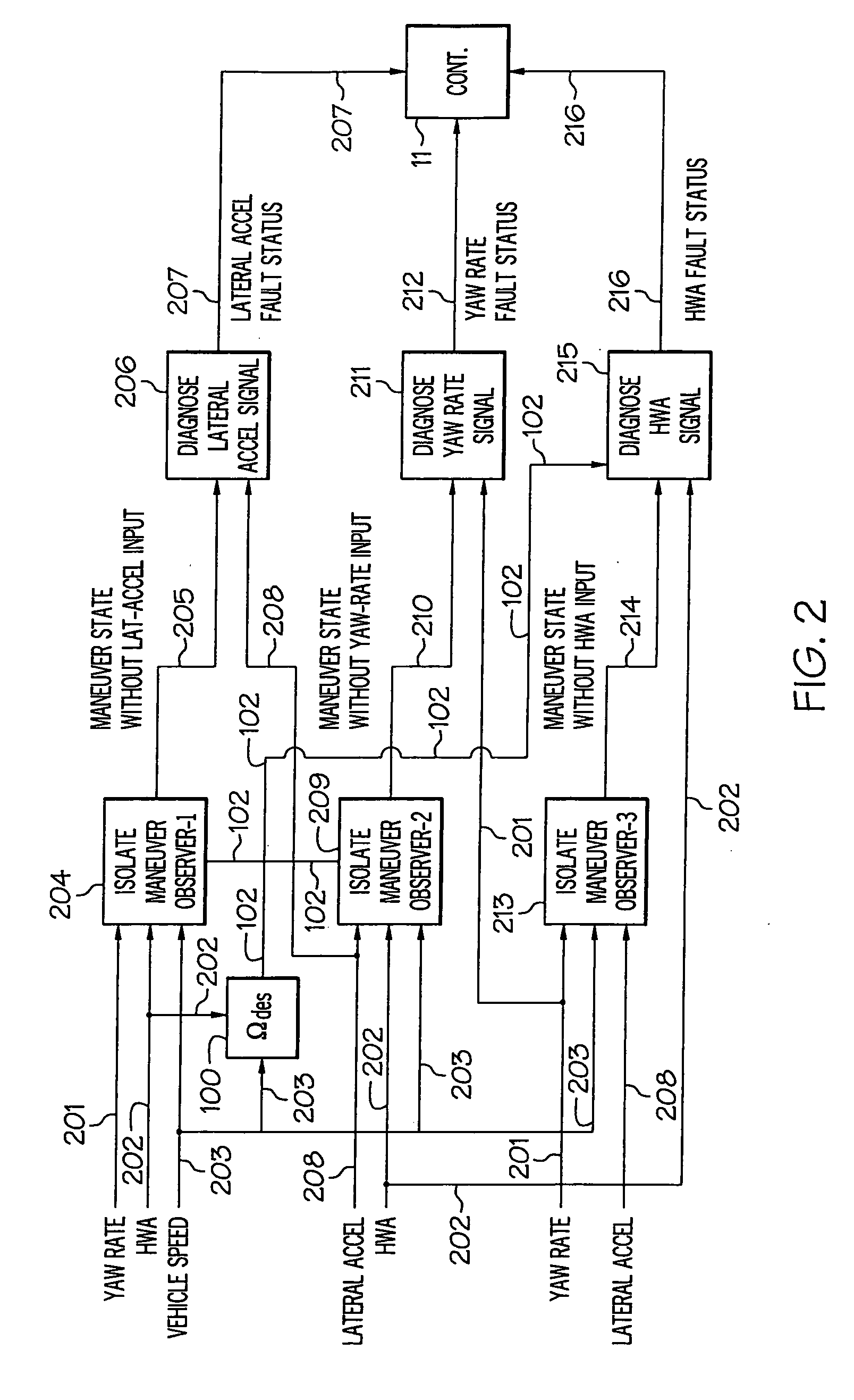
[0006] In one aspect, a vehicle stability control system diagnostic strategy, may include a diagnostic strategy that is adaptively applied based upon the identified maneuver states of the vehicle. The diagnostic architecture may contain three vehicle state observers (i.e., models), each based on inputs from only two of the three sensors (yaw rate, lateral acceleration and hand wheel angle). More particularly, the first observer may not consider lateral acceleration input. The second observer may not consider yaw rate sensor input and the third may not consider hand wheel angle (HWA) sensor input in determining the vehicle state. However, estimated vehicle speed input may be used by all the observers. For example, the first observer may detect a maneuver state based on yaw rate and HWA and vehicle speed inputs. Then, it may diagnose the lateral acceleration sensor failure based on the observer output. The diagnostics may be based on vehicle dynamics correlations that hold in steady state linear range conditions. Similarly, the other two observers may detect maneuver state and diagnose the respective signals. Advantageous variants may include the use of a proactive sensor diagnostics strategy that provides increased coverage during steady state linear range maneuvers while simultaneously detecting faults within the required fault response time.

Problems solved by technology

ESP system safety analysis has identified that sensor faults, specifically faults of the yaw rate, lateral acceleration and hand wheel angle signals, require detection within a short period of time.
Those faults resulting in erroneous sensor outputs, but still within the normal range of the measured signals, are more difficult to detect, and are the subject of this disclosure.
The first drawback with this strategy is that it is a reactive approach to a fault rather than a proactive one.
If it is a sensor failure that caused an unwanted activation, this strategy can wait several seconds before declaring it a fault.
The second drawback is that it can declare a false fault if the vehicle is in a true ESP maneuver for a prolonged period, even when there is no true fault (for example, in case of testing, demo, etc.).
The third drawback is that it does not monitor sensor condition during normal driving.

Method used


Image

  • Adaptive maneuver based diagnostics for vehicle dynamics
  • Adaptive maneuver based diagnostics for vehicle dynamics
  • Adaptive maneuver based diagnostics for vehicle dynamics

Examples


example 1

[0074] The above strategy was tested exhaustively in simulation using a validated vehicle simulation model representing a pick up truck with a hydraulic brake system. The tests included steady state linear and aggressive emergency maneuvers on different surfaces. The results did not show any false diagnosis of a sensor fault. And when a fault was injected, it was isolated and detected correctly within the required fault response time specified by the system safety hazard analysis activity.

[0075] In Example 1, the vehicle was placed in a transient emergency maneuver condition on a slippery, icy surface, and the algorithm results (see FIGS. 6-14) showed all observers (see FIGS. 9 and 13-14) successfully identified the maneuver state and the diagnostics (see FIG. 8) did not falsely declare a fault.

example 2

[0076] In Example 2, the vehicle was located on a dry surface having a constant radius turning maneuver condition wherein a slow changing lateral acceleration fault was injected (see FIG. 16), and the algorithm results (see FIGS. 15-22) showed all observers (see FIG. 18) successfully identified the maneuver state (i.e., without a measured lateral acceleration input) and the diagnostics (see FIG. 18) successfully detected the lateral acceleration signal fault.

example 3

[0077] In Example 3, the vehicle was located on a dry surface having a straight driving maneuver condition wherein a yaw rate fault was injected (see FIG. 28), and the algorithm results (see FIGS. 23-33) showed all observers (see FIG. 26) successfully identified the maneuver state (i.e., without a measured yaw rate input) and the diagnostics (see FIG. 26) successfully detected the yaw rate signal fault.


PUM


Abstract

A vehicle stability control system diagnostic strategy, wherein the diagnostic strategy may be adaptively applied based upon the identified maneuver states of the vehicle. The diagnostic architecture contains three vehicle state observers (i.e., models) each based on inputs from only two of the three sensors (yaw rate, lateral acceleration and hand wheel angle). More particularly, the first observer does not consider lateral acceleration input. The second observer does not consider yaw rate sensor input and the third does not consider hand wheel angle (HWA) sensor input in determining the vehicle state. However, estimated vehicle speed input is used by all the observers. For example, the first observer detects a maneuver state based on yaw rate and HWA and vehicle speed inputs. Then it diagnoses the lateral acceleration sensor failure based on the observer output. The diagnostics are based on vehicle dynamics correlations that hold in steady state linear range conditions. Similarly, the other two observers detect maneuver state and diagnose the respective signals. Advantageous variants include the use of a proactive sensor diagnostics strategy that provides increased coverage during steady state linear range maneuvers while simultaneously detecting faults within the required fault response time.

Description

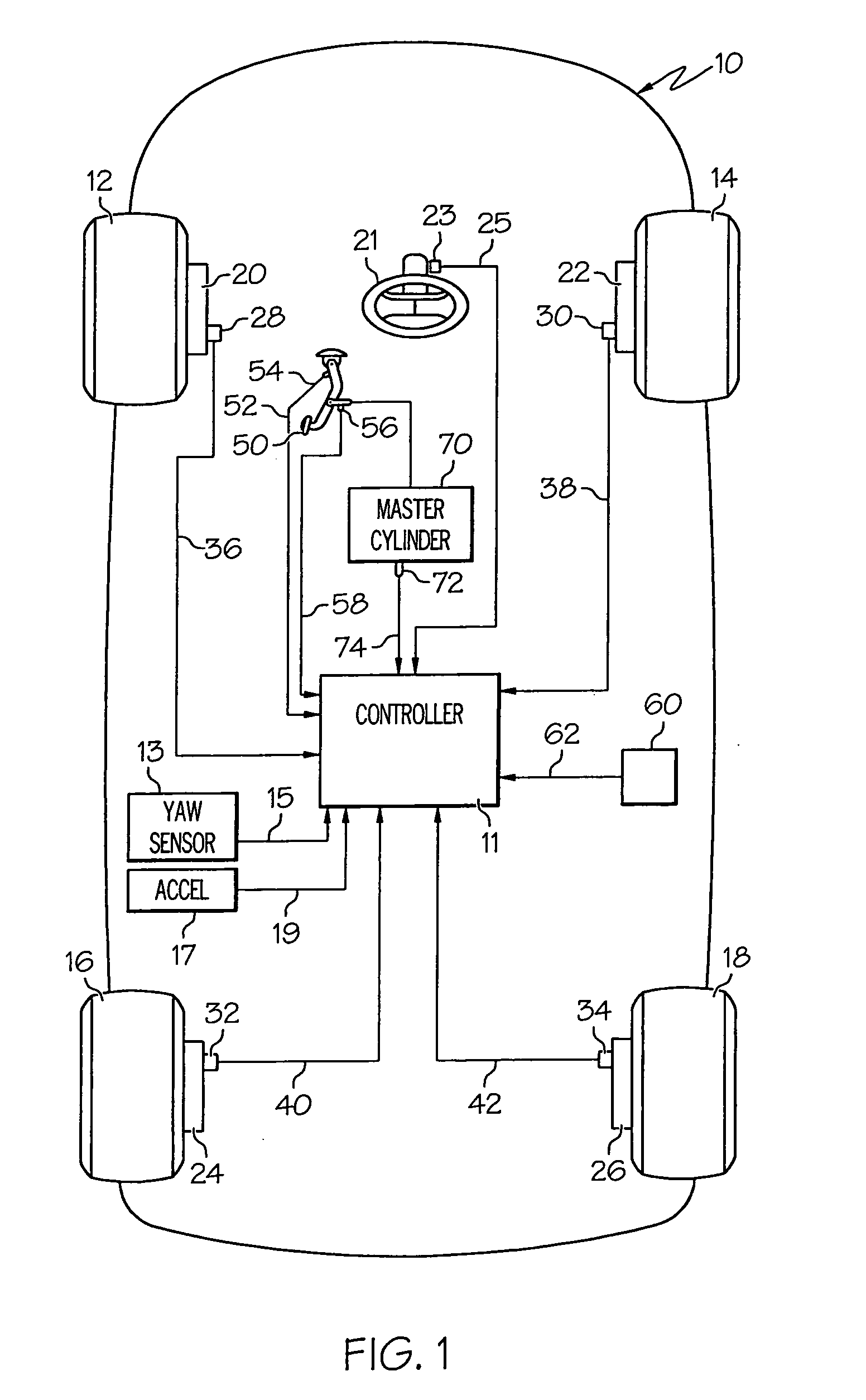
BACKGROUND [0001] The disclosure is directed to vehicular stability control, and more particularly, to a method for enhancing vehicle stability control. [0002] A vehicle stability control (VSC) system works by detecting when a driver has lost some degree of control. These systems are also known as ESP (electronic stability program) systems or VSE (vehicle stability enhancement) systems in the art. These systems automatically stabilize the vehicle to help the driver regain control. A central processor takes information from a number of sensors, and then determines whether the car is in a stable or unstable state. By combining the data from wheel speed sensors, steering angle sensors, yaw rate sensors (measuring the amount a vehicle rotates around its vertical center axis), and lateral acceleration sensors (measuring the amount of sideways acceleration generated by the vehicle), the central processing unit can actually detect when a vehicle is behaving in a way inconsistent with how t...

Claims


Application Information

Patent Timeline
Patent Type & Authority Applications(United States)
IPC IPC(8): G06G7/76
CPCB60W2520/14B60W50/0205
Inventor SUNDARAM, PADMAHAC, ALEKSANDER B.
Owner BWI CO LTD SA
Learn More