Cube corner retroreflector with limited range
a retroreflector and cube corner technology, applied in the field of retroreflectors, can solve the problems of limited intensity of reflected light, avoid excessive road preview, selectively limit the range at which the article is located, and avoid distraction of the driver
- Summary
- Abstract
- Description
- Claims
- Application Information
AI Technical Summary
Benefits of technology
Problems solved by technology
Method used
Image
Examples
example 1
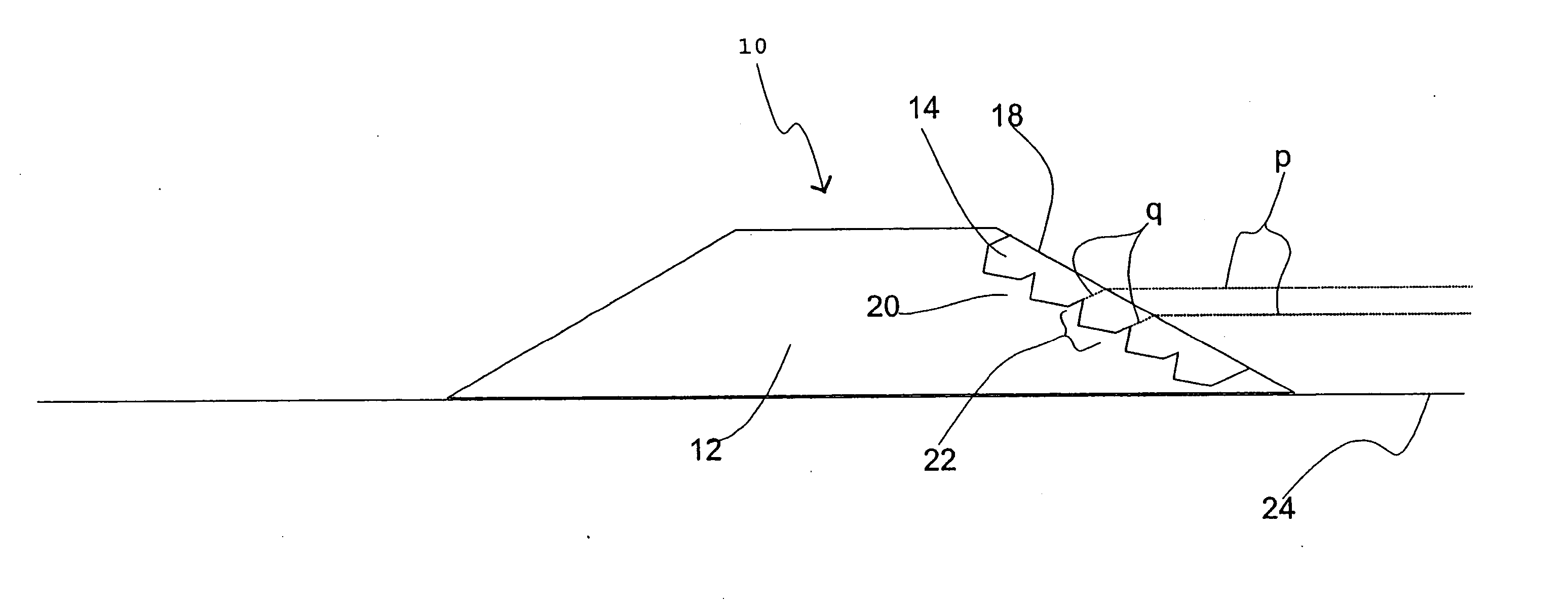
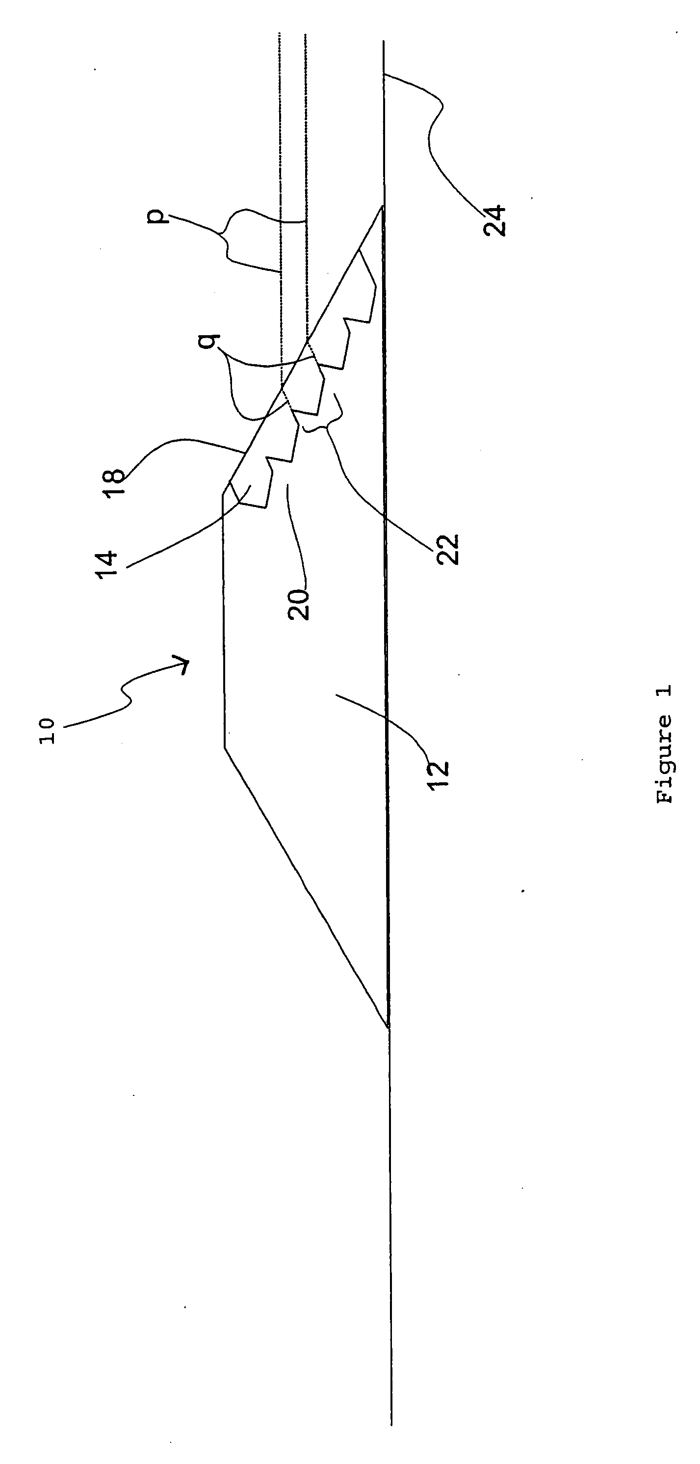
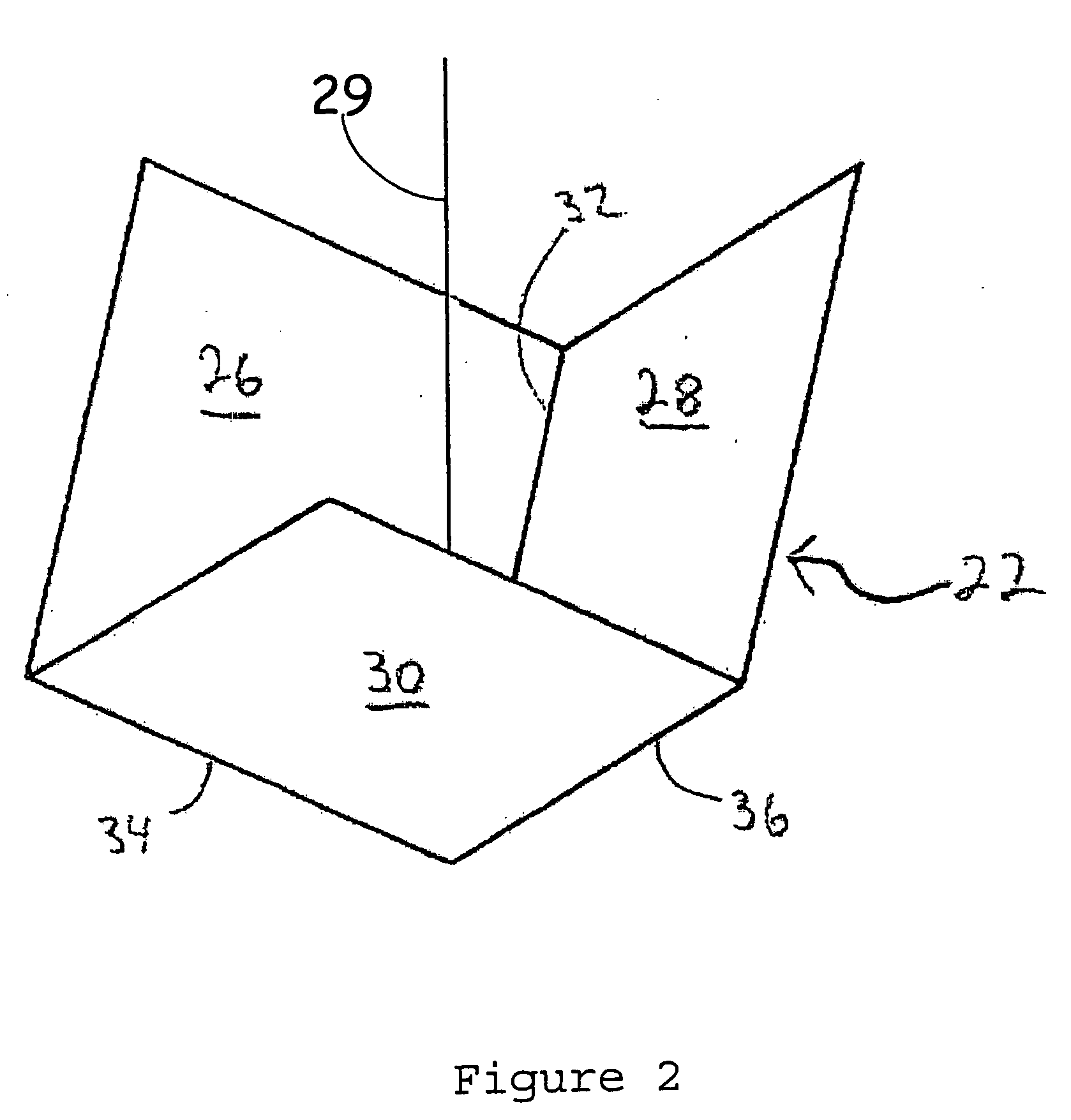
[0117] A retroreflective article in accordance with the present invention can be made with cube corner elements 22, oriented as in FIG. 4A or 4B, that direct the retroreflected intensity away from observation angles between 0 and 0.2 degrees. In this case, 0.2 degrees is the observation angle selected to represent “too far”; 0.4 degrees is selected to represent “far enough”; 1.0 degree is selected to represent “close enough”. A tool having dihedral angle errors of about +0.04 degrees, about −0.09 degrees, and about +0.07 degrees can be used to mold acrylic resin in a process that transforms dihedral angle errors by about −0.04 degrees, about −0.04 degrees, and about −0.07 degrees, respectively, to produce cube corner elements 22 having idealized dihedral angle errors of about 0 degrees, about −0.13 degrees, and about 0 degrees. The tool used to produce this cube corner element has the retroreflected spot pattern of FIG. 9A. The molded cube corner element in a raised pavement marker ...
example 2
[0125] This example will satisfy the driver-on-left criterion instead of the international criterion. The molded cubes of Example 1 having dihedral angle errors {0, −0.13, 0} are called A-cubes. Molded cubes having dihedral angle errors {−0.13, 0, +0.13} are called B-cubes. Molded cubes having dihedral angle errors {+0.13, 0, +0.13} are called C-cubes. FIG. 9C shows the spot patterns from the A-cubes. FIG. 15A shows the spot pattern from the B-cubes. FIG. 15B shows the spot pattern from the C-cubes. The B-cube puts two spots where the C-cube corner puts one, and vice versa. The B-cube pattern and C-cube pattern partly coincide with the pattern from the A-cubes.
[0126] If the molding transformation is {−0.04, −0.04, −0.07} then in the tool, A-cubes have dihedral angle errors {+0.04, −0.09, +0.07}, B-cubes have dihedral angle errors {−0.09, +0.04, +0.20} and C-cubes have dihedral angle errors {+0.17, +0.04, +0.20}.
[0127] Either A-cubes , B-cubes, or C-cubes will satisfy the driver-on...
example 3
[0131] This example has an extended retroreflection pattern, by means of mixing two spot patterns of different scales. FIG. 10 shows the addition of the spot pattern, shown with solid dots, corresponding to dihedral errors {−0.02°, 0.12°, 0.04°} to the spot pattern, shown with hollow dots, corresponding to dihedral errors {−0.03°, 0.18°, 0.06°}. The second pattern is exactly 1.5×the size of the first. Note that the cubes in the tool used to make these two patterns will not themselves exhibit patterns differing in scale. For example, if the molding transformation is {−0.04°, −0.04°, −0.07°}, then the cubes in the tools will be {0.02°, 0.16°, 0.11°} and {0.01°, 0.22°, 0.13°} which are not proportionate.
[0132] Combination of patterns of different size accommodates the variation with road distance of the positions of the of the observer relative to the headlights as shown in FIG. 11. A lens comprised of macrocubes will have between about 100 and about 300 cube corners, allowing much fl...
PUM
| Property | Measurement | Unit |
|---|---|---|
| dihedral angle errors | aaaaa | aaaaa |
| dihedral angle | aaaaa | aaaaa |
| dihedral angle | aaaaa | aaaaa |
Abstract
Description
Claims
Application Information
 - R&D
- Intellectual Property
- Life Sciences
- Materials
- Tech Scout
- Unparalleled Data Quality
- Higher Quality Content
- 60% Fewer Hallucinations
Browse by: Latest US Patents, China's latest patents, Technical Efficacy Thesaurus, Application Domain, Technology Topic, Popular Technical Reports.
© 2025 PatSnap. All rights reserved.Legal|Privacy policy|Modern Slavery Act Transparency Statement|Sitemap|About US| Contact US: help@patsnap.com


