
Cordless Screwdriver

a cordless screwdriver and screwdriver technology, applied in the direction of screwdrivers, power-driven tools, wrenches, etc., can solve the problems of cordless screwdrivers, screwdrivers become partly discharged, devices are often not ready for use,

Inactive Publication Date: 2007-11-08
ROBERT BOSCH GMBH
View PDF15 Cites 84 Cited by
  • Summary
  • Abstract
  • Description
  • Claims
  • Application Information

AI Technical Summary

Benefits of technology

The present invention is a cordless screwdriver that solves the problems of previous generations, such as slow charging times, limited battery life, and the need for separate charging shells. The invention has a unique design that allows for multiple power circuits to be switched on and off independently of each other using a single toggle switch. This design prevents unintentional discharging of the battery and allows for easy switching between different functions, such as a work light and motor rotation. The invention also has a compact and secure coupling between the motor and gear, a long toggle switch for easy switching, and a hexagonal socket for quick and simple replacement of different tools. The invention is lightweight and ergonomic, with a reduced size and weight of the motor and battery. The lithium-ion battery used in the invention has almost no self-discharge, making the cordless screwdriver ready for use even after long periods of non-use.

Problems solved by technology

As a result, the device is often not ready for use precisely when it is needed, and the well-known memory effect is a further disadvantage NiCd cells discharge after a certain length of time without outputting power, and even unused cordless screwdrivers become partly discharged after a short time.
A further disadvantage of the known cordless screwdrivers is their voluminous size because of large structural components, such as the gear, switch system, and the rechargeable battery in the form of NiCd cells, whose ⅘ sub-C size when located in the pistol grip is an impairment to ergonomics and utility, since narrow, angled places where screwing is to be done cannot be reached.
A disadvantage is that for that purpose, a separate actuating element must first be operated.
If by mistake this element is not switched off, the battery discharges unintentionally.

Method used


Image

  • Cordless Screwdriver
  • Cordless Screwdriver
  • Cordless Screwdriver

Examples


Embodiment Construction

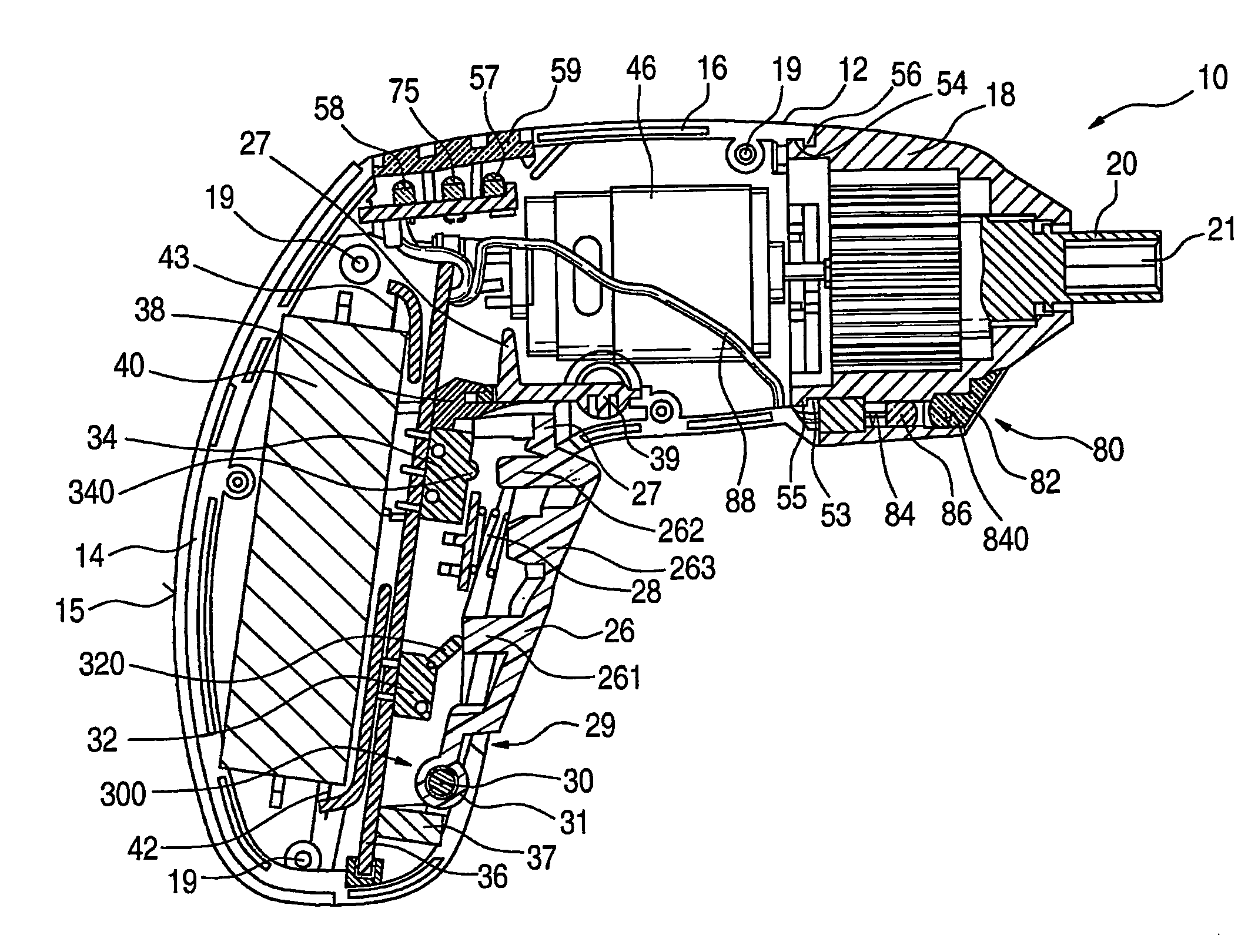
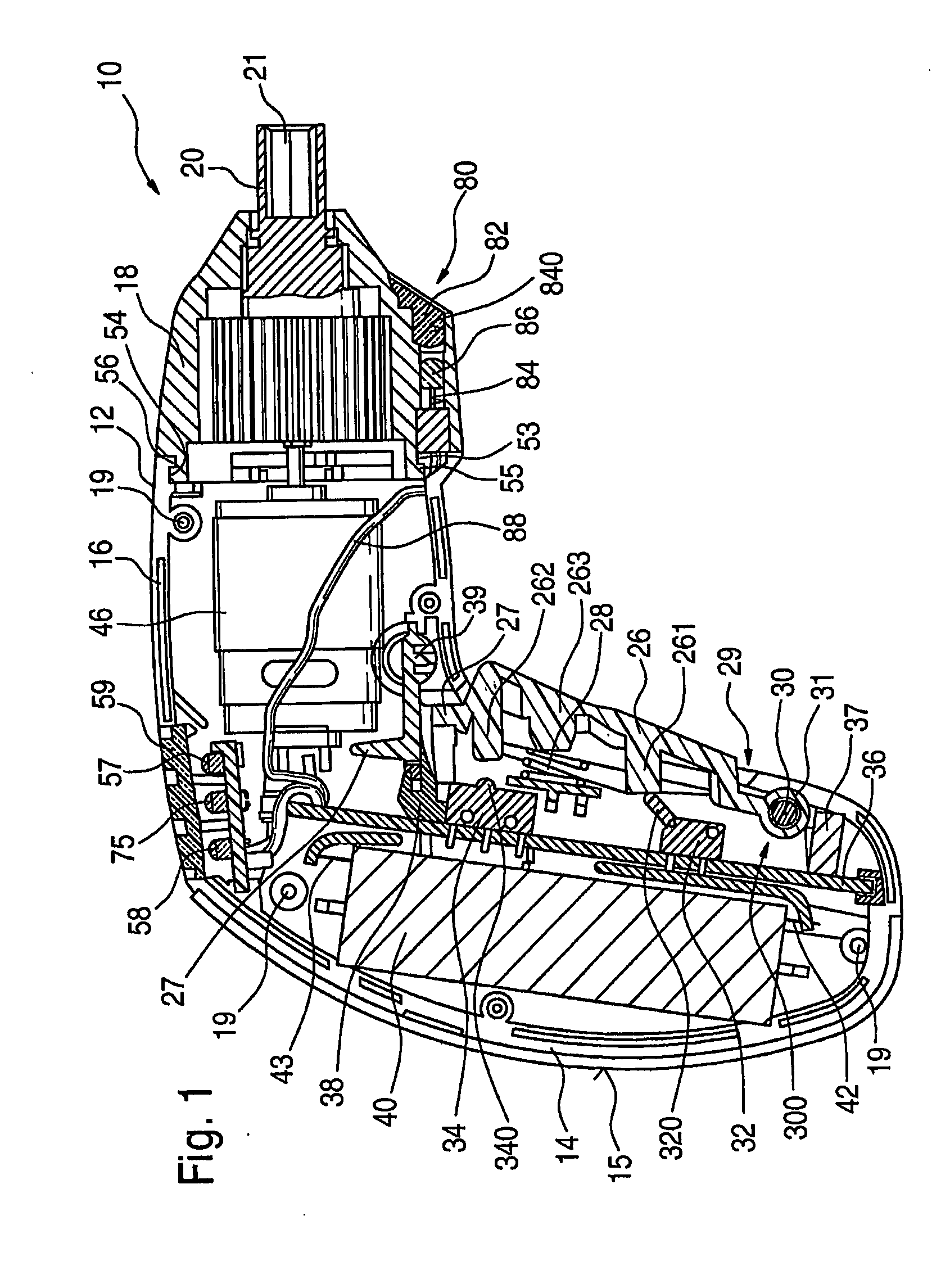
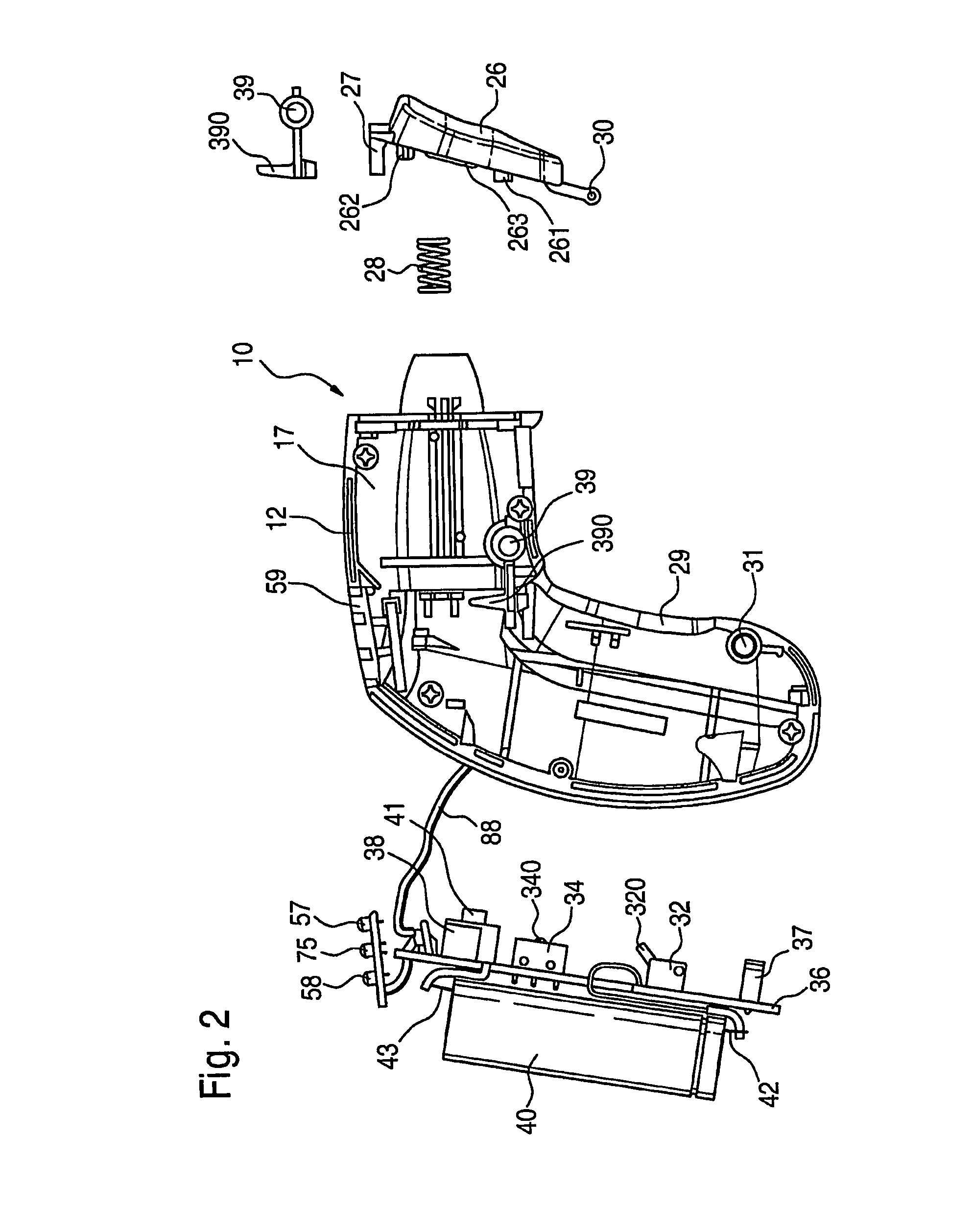
[0036]FIG. 1 shows a pistol-shaped cordless screwdriver 10 with a motor housing 12, aligned with the screwing direction, and a pistol grip 14 angled from it. The motor housing 12 with the pistol grip 14 is formed from two half shells 16, 17, which can be put together, braced tightly against one another, in a center plane 15 (FIG. 4). To that end, four screws reach through bores in one half shell 17 into four screw domes 19 of the other half shell 16 and firmly hold the two against one another; in FIG. 1, the upper or right-hand half shell 17 has been removed to make it possible to see into the interior of the housing 12, received only by the left-hand half shell 16.

[0037] A toggle switch 26 is located on the pistol grip 14, extending over a large area of its front face end; because of its great length, this toggle switch permits convenient switching on and off of the cordless screwdriver 10, even when it is held in difficult positions in the user's hand.

[0038] For inserting the to...


PUM


Abstract

The invention relates to a battery-driven screwdriver comprising a housing (12, 18) provided with a handle (14), an on / off switch (26) and, particularly, a permanently fixed rechargeable battery (40) and charge contact tongues (37) which are associated with the rechargeable battery (40). The battery-driven screwdriver is characterised in that it is safe and comfortable to use due to the on / off switch (26) being mounted in a pivotable manner and extending in a longitudinal manner over the innerside of the handle (14), said on / off switch being able to be successively interrupted and / or closed, independently from each other, during the actuation stroke of several electric circuits of the battery-driven screwdriver (10).

Description

PRIOR ART [0001] The present invention is based on a cordless screwdriver as generically defined by the preamble to claim 1. [0002] Cordless screwdrivers are already available in the power class between 2.4 V and 3.6 V, as known for instance from European Patent Disclosure 1 066 930. They usually have a plurality of NiCd cells as energy storing means; an ON / OFF button with a short toggle switch and without continuously variable speed governing, and a switch for switchover from counterclockwise to clockwise operation; a gear, in particular a planetary gear, that steps down the motor rpm; and a motor with a standard diameter of 27.5 mm. There are both rodlike and pistol-shaped versions as well as versions with an adjustable-angle handle. For charging, these devices are connected to the charger either via a plug—in a way similar to a cell phone or electric shaver—or via a mount with contacts, into which contacts the rechargeable battery can be placed for charging. The mounts can be sec...

Claims


Application Information

Patent Timeline
Patent Type & Authority Applications(United States)
IPC IPC(8): H01H13/72B25B21/00B25B23/18B25F5/02
CPCB25B21/00B25F5/021B25F5/02B25B23/18
Inventor LOHR, GUENTERROEHM, HEIKOHIRSCHBURGER, WOLFGANGKAGELER, SVENZULFIKAR, ABDUL AZIZYEOH, SIM TEIKLIM, JOSEPH SIANG CHOON
Owner ROBERT BOSCH GMBH
Learn More