
Styled the system, asymmetric, engine/pump design

a technology of engine/pump and system, applied in the direction of connecting rods, bearings, shafts and bearings, etc., to achieve the effect of increasing and decreasing the effective/functional working length of the crank, increasing the discreet energy efficiency/fuel economy, and increasing the net work outpu

Inactive Publication Date: 2007-11-08
ETHELMER PFLUGHOEFT STEPHEN ANTONIUS
View PDF6 Cites 11 Cited by
  • Summary
  • Abstract
  • Description
  • Claims
  • Application Information

AI Technical Summary

Benefits of technology

[0065] This, the first (Claim #1) improvement, can, in and of and by itself, materially increase the discreet energy efficiency / fuel economy as applied to use in heat / pressure engines so designed and built.
[0067] This extra / additional sub-link will alternately increase and decrease the effective / functional working length of the crank (crankshaft arm) as this part rotates, with the sole specific intent of fundamentally altering / changing the vectors and forces transmitted during the working cycles.
[0068] This, the second (Claim #2) improvement can, in and of and by itself, greatly increase the discreet energy efficiency / fuel economy as it is applied to use in heat / pressure engines, and considerably so as it is applied to use in pumping / compressing machines, and materially so as it is applied to use in material forming / cutting machines (machine tools).
[0070] The advantages of my invention are twofold. The first being to greatly increase the net work output per specific energy input as compared to the older, considerably less efficient and now obsolete symmetric design type engines, pumps, and machine tools. The second of the advantages is, with engines, that the size, weight, and cost can be greatly reduced per net specific output.

Problems solved by technology

However this differential pressure may be brought about, or caused, or induced is utterly irrelevant to this writing and has not been nor will be addressed here.

Method used


Image

  • Styled the system, asymmetric, engine/pump design
  • Styled the system, asymmetric, engine/pump design
  • Styled the system, asymmetric, engine/pump design

Examples


Embodiment Construction

[0088] What is Old

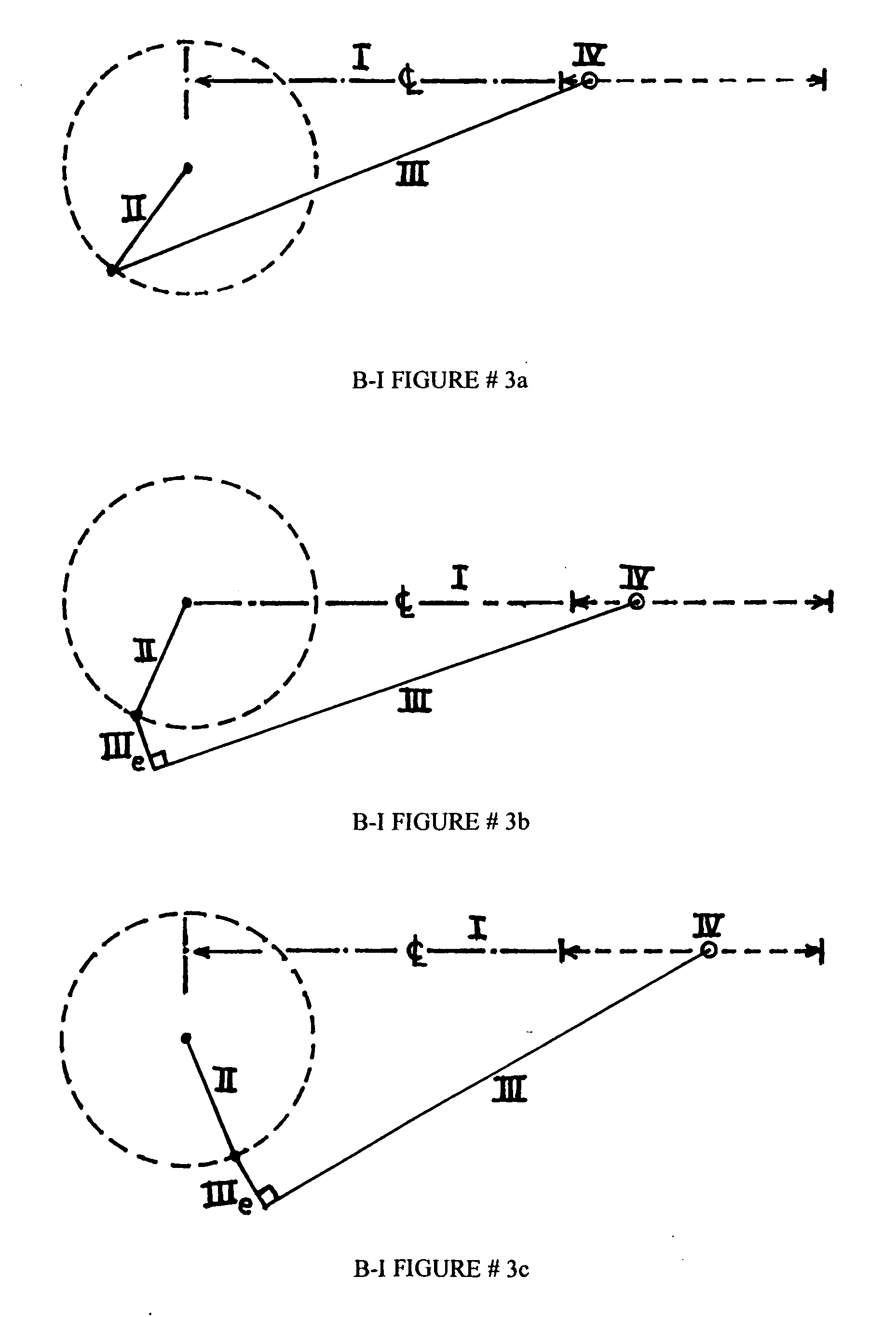
[0089] With the slider / crank type of the quadric-crank mechanism—a line described along / through the nominal geometric center axis of the line of travel of the slider / bearing portion or part of the mechanism and extended through the area of the center (central rotating) axis of the crank (crankshaft) will (almost) invariably intersect the (line of the) geometric center (or central rotating) axis of the crankshaft (B-I FIG. 3).

[0090] Since this line of the slider / bearing travel axis effectively bisects the physical structure of the mechanism (machine) into two equal or mirror image parts, this old and now obsolete design will be called or referred to as the symmetric mechanism, or symmetric structure, or symmetric pattern, etc.

[0091] The very few (if any) heat / pressure engines that diverge from this classic pattern do so solely and exclusively in order to moderate / dampen / reduce / eliminate harmonic vibrational buildup in the motion works and the damaging and destruc...


PUM


Abstract

What is new in the art (or rather, technique) in the structuring of the linkage mechanism as it is most commonly used in the design of reciprocating piston heat / pressure engines and pumping / compressing machines are the two alterations and the combination thereof that I have invented. They are, #1, establishing a (very large) fixed and permanent offsetting, or asymmetry, between the geometric center axi of the cylinder and crankshaft for the purpose of altering the fundamentals of the working cycle, #2, the addition of a sub-link to the connecting rod such that it then also functions as an extension (alternately increasing and decreasing the working, or effective length) of the crankshaft arm during the rotation of the crankshaft, and #3, the combining of these two improvements as one unit, or in one machine.

Description

CROSS-REFERENCES TO RELATED (PATENT) APPLICATIONS [0001] N / A STATEMENT REGARDING FEDERALLY SPONSORED RESEARCH AND / OR DEVELOPMENT [0002] N / A REFERENCE TO SEQUENCE LISTING, A TABLE, OR A COMPUTER PROGRAM LISTING COMPACT DISC APPENDIX [0003] N / A BACKGROUND OF THE INVENTION [0004] The field of endeavor, or technical field, or field of invention to which this, my invention pertains is Mechanical Engineering, the sub-field (or sub-class) perhaps being Linkages, Mechanisms, Machines, and Structures. [0005] Correctly speaking, this, my invention, is two improvements and their combination in the slider / crank type of the quadric-crank mechanism which is universally known of in the form of the reciprocating piston internal combustion engine. [0006] A Listing of Definitions [0007] Links, in mechanics, are nothing more or less than straight-line bars (refer also to VECTORS, in mathematics and mechanics). [0008] Linkages, in mechanics, are combinations of such links, in general connected by pins,...

Claims


Application Information

Patent Timeline
IPC IPC(8): F02B75/24F02B75/32
CPCF16C7/02F02F7/0019
Inventor ETHELMER PFLUGHOEFT, STEPHEN ANTONIUS
Owner ETHELMER PFLUGHOEFT STEPHEN ANTONIUS
Learn More