Method and apparatus for operation of a power station

a power station and power supply technology, applied in the direction of mechanical power/torque control, turbine/propulsion engine cooling, piston engine recoiling, etc., can solve the problems of high loss of compressor flow, power consumption from electrical grid system, etc., and achieve the effect of rapid reaction, high rotation speed and high rotation speed

Active Publication Date: 2007-11-01
GENERAL ELECTRIC TECH GMBH
View PDF13 Cites 24 Cited by
  • Summary
  • Abstract
  • Description
  • Claims
  • Application Information

AI Technical Summary

Benefits of technology

[0005] In one aspect, exemplary methods are disclosed for operating a power station, which comprises a power-consuming shaft run and a power-emitting shaft run, such that at least one of the shaft runs is operated at an asynchronous rotation speed with respect to the grid system in a steady operating state, in which case, in contrast for example to machines which are operated at half the grid system frequency, the ratio between the frequency of the AC grid system and the rotation speed of the shaft run is not an integer. During steady state operation such as this, at least one electrical machine, which is being operated at an asynchronous rotation speed with respect to the grid system, is connected to the electrical grid system. In one exemplary embodiment, the rotation speed of an electrical machine is varied while it is connected to the electrical grid system. Such exemplary methods as disclosed allow the power consumption or power emission of a shaft run to be regulated particularly efficiently via its rotation speed. The power consumption or power emission of the entire power station can in this way be highly efficiently matched to the demands from the electrical grid system. Furthermore, such exemplary methods make it possible to react to changes in the power demands very quickly. This can be possible when a means for frequency variation, for example a static frequency converter SFC, is arranged between the electrical machine and the electrical grid system.
[0009] In another exemplary method, which can be used when there is a positive power demand from the grid system, e.g., when the power station is in the power mode, in which power is emitted to the grid system, the rotation speed of the power-emitting shaft run is increased when the power demand rises, and the rotation speed of the power-emitting shaft run is reduced when the power demand decreases, with the generator being connected to the grid system all the time. In yet another exemplary method, which can be used when there is a negative power demand from the grid system, with power being taken from the grid system, e.g., in the charging mode of the power station, the rotation speed of the power-consuming shaft run is reduced when the power demand increases, and the rotation speed of the power-consuming shaft run is increased when the power demand falls, with the motor being connected to the grid system all the time.
[0010] In yet another embodiment of the method, power is additionally taken from the grid system, and a storage fluid which is contained in the storage volume is heated. This makes it possible to react very quickly to a falling power demand in the grid system. In one embodiment, when the power demand from the grid system falls, the heating power taken from the grid system is increased, and the rotation speed and thus the power consumption of the power-consuming shaft run are increased, and the heating power is reduced again. It is likewise possible when the power demand from the grid system is falling for the heating power which is taken from the grid system to be increased in the power mode, for the rotation speed and thus the power emitted from the power-emitting shaft run to be successively reduced, and for the heating power to be reduced again.

Problems solved by technology

Furthermore, the constriction of flow to the compressor is highly lossy.
In this case, power is consumed from the electrical grid system.

Method used


Image

  • Method and apparatus for operation of a power station
  • Method and apparatus for operation of a power station

Examples


Embodiment Construction

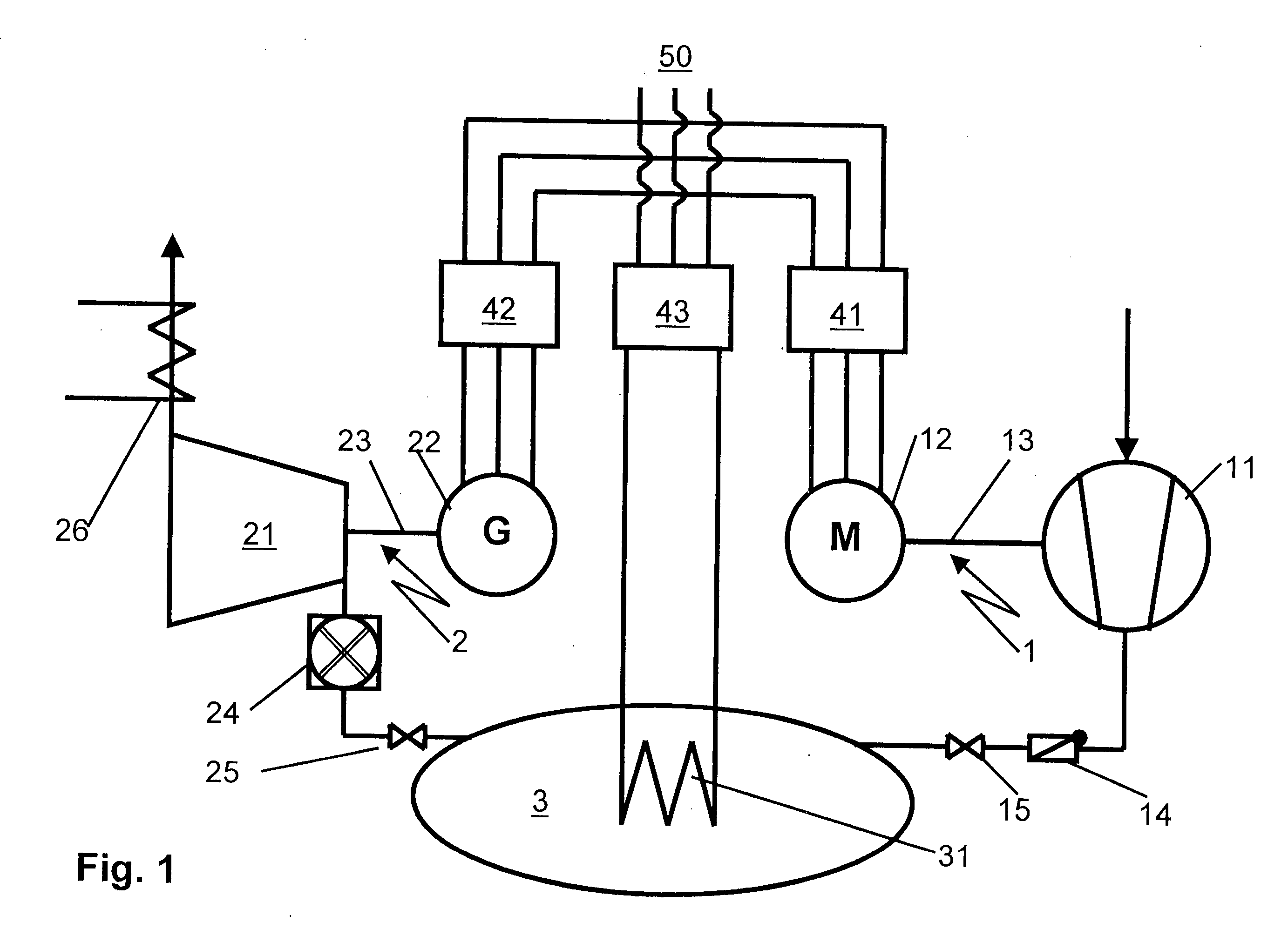
[0015]FIG. 1 illustrates an exemplary power station which is suitable for carrying out the exemplary method as disclosed. Such an exemplary power station comprises a power-consuming shaft run 1, a power-emitting shaft run 2 and a storage volume 3. A compressor 11 and a drive motor 12 are arranged on a common shaft 13 on the power-consuming shaft run. An expansion machine 21 and a generator 22 are arranged on a common shaft 23 on the power-emitting shaft run. It is not necessary for all of the machines which are arranged on one shaft run to be arranged on a common shaft; for example, clutches or transmissions can be arranged without any problems in the shaft run and allow the machines on one shaft run to be operated at different rotation speeds to one another. The illustrated power station can be operated not only to consume power but also to emit power in an electrical grid system 50. In this case, on the one hand, the power consumption of the compressor 11 is greater than the power...


PUM

PropertyMeasurementUnit
frequencyaaaaaaaaaa
storage volumeaaaaaaaaaa
rotation speedaaaaaaaaaa

Abstract

A power station comprises a power-consuming shaft run on which a motor and a compressor are arranged, as well as a power-emitting shaft run on which a generator and an expansion machine are arranged. The compressor feeds a compressed fluid into a storage volume. The compressed storage fluid is expanded in the expansion machine, producing work. The generator and the motor are connected to the electrical grid system via frequency converters. This makes it possible to operate the electrical machines at a rotation speed which is asynchronous with respect to the grid system. A method and apparatus is disclosed that allows the net power output of the power station to be matched to the demands of the electrical grid system by varying the rotation speed of at least one of the shaft runs.

Description

CROSS REFERENCE TO RELATED APPLICATIONS [0001] This application claims priority under 35 U.S.C. §119 to German Application 10 2004 028 530.6 filed in Germany on 11 Jun. 2004, and as a continuation application under 35 U.S.C. §120 to PCT / EP2005 / 052666 filed as an International Application on 09 Jun. 2005 designating the U.S., the entire contents of which are hereby incorporated by reference in their entireties.FIELD [0002] A method and apparatus is disclosed for operation of a power station. BACKGROUND INFORMATION [0003] By way of examples in the prior art, US 2003 / 0131599 discloses air-storage power stations in which a compressor compresses air in times in which the electricity demand is low, and feeds this to a storage volume. The air stored there is expanded, producing work, in times of high electricity demand, in an expansion machine, for example a turbine. In this case, the expansion machine drives a generator which supplies power to an electrical grid system. Power stations suc...

Claims


Application Information

Patent Timeline
Patent Type & Authority Applications(United States)
IPC IPC(8): F01B21/04G05D13/02B01D5/00F01K25/06F02C6/16F02C7/18H02P9/44H02P9/48
CPCY02E60/15F02C6/16Y02E60/16
Inventor ALTHAUS, ROLF
Owner GENERAL ELECTRIC TECH GMBH
Why Eureka
Try Eureka