
Wirefree intercom having low power system and process

a technology of low power consumption and intercom, applied in the field of wirefree intercom, can solve the problems of distorted or destroyed signals, limited range of power line modulation techniques of intercoms, and often limited sound quality, and achieves clear sound quality, long range, and low power consumption.

Inactive Publication Date: 2007-11-01
THE CHAMBERLAIN GRP INC
View PDF39 Cites 15 Cited by
  • Summary
  • Abstract
  • Description
  • Claims
  • Application Information

AI Technical Summary

Benefits of technology

[0006] It is a principal object and advantage of the present invention to provide a wirefree intercom system that avoids the need for line power.
[0007] It is another object and advantage of the present invention to provide a wirefree intercom system that has low power consumption.
[0008] It is an additional object and advantage of the present invention to provide a wirefree intercom system having an unlimited number of units.
[0009] It is a further object and advantage of the present invention to provide a wirefree intercom system that provides secure conversation.
[0010] It is another object and advantage of the present invention to provide a wirefree intercom that is not affected by line noise.
[0011] It is an additional object and advantage of the present invention to provide a wirefree intercom system that has a long range.

Problems solved by technology

These intercoms use power line modulation techniques and have limited ranges due to the need for physical attachment to the power lines in the wall, as well as when the possibility of phase changes in the power connection that may interfere with the signal.
In addition, the sound quality is often limited in such systems, and when there is a motor (such a hair dryer or vacuum cleaner) also in operation on the circuit, the signal is often distorted or destroyed.
However, such devices do not provide security when multiple devices are employed in a dwelling.
In a business environment, this loss of security is not desirable.
Additionally, such devices consume too much power and are thus not feasibly implemented without a direct power connection to a wall outlet.
In addition to limitation described above with respect to wireless intercoms, the batteries in such systems will only last about a day or two when the device is left on.

Method used


Image

  • Wirefree intercom having low power system and process
  • Wirefree intercom having low power system and process
  • Wirefree intercom having low power system and process

Examples


Embodiment Construction

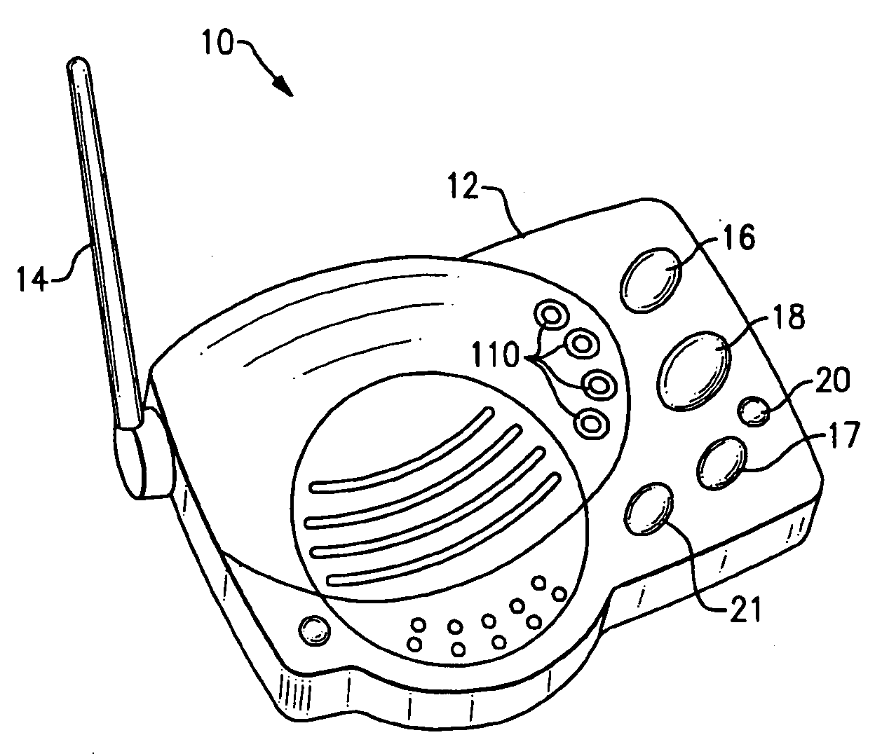
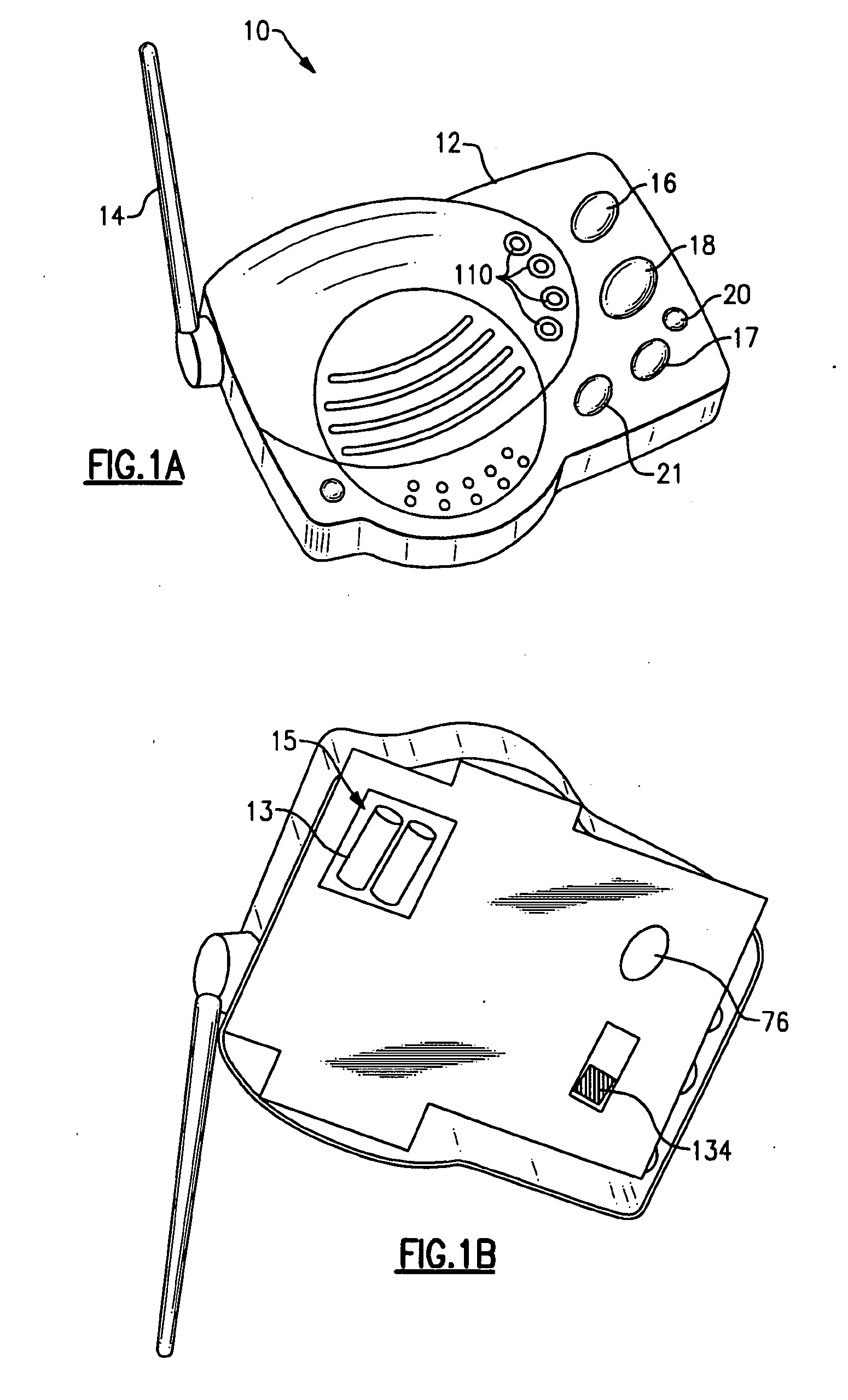
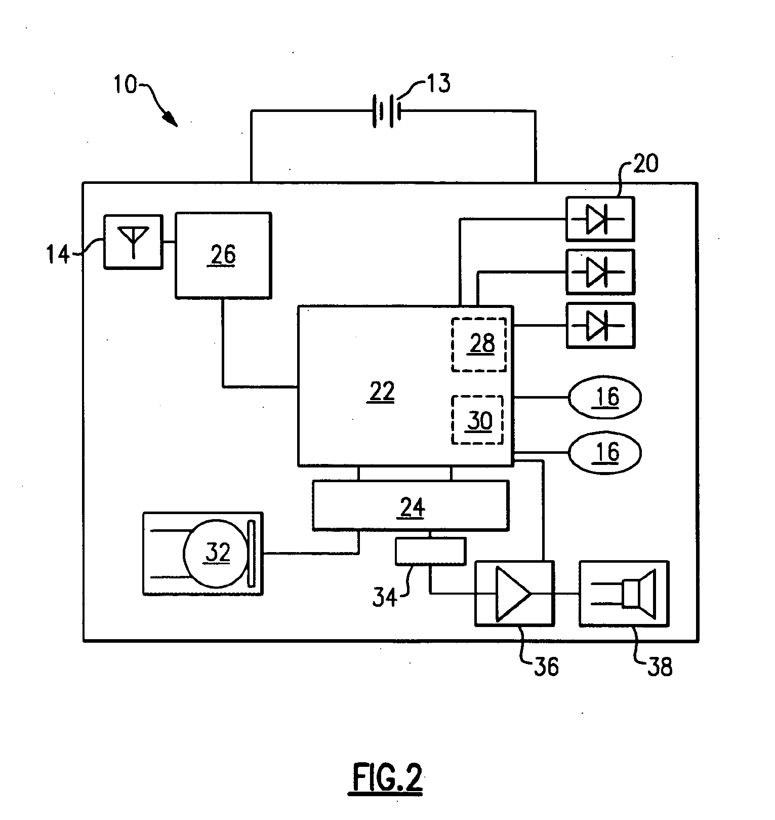
[0026] Referring now to the drawings, wherein like numerals refer to like parts throughout, there is seen in FIGS. 1A and 1B a wirefree intercom 10 according to the present invention. Intercom 10 comprises a base unit 12 and an antenna 14 attached thereto. Base unit 12 houses the circuitry for providing wireless intercom capabilities, without the need for line power or excessive battery power usage, as will be described hereinafter. Base unit 12 further houses a power source, such as a conventional battery 13, which may be received in a compartment 15 formed into the bottom of base unit 12. Base unit 12 may further include a channel select button 16, which allows a user to cycle through the preselected channels or select all of the preselected channels for transmission and reception. Intercom 10 may further comprise any number of illuminating regions 17, such as LEDs, for reflecting the current operating mode of base unit 12, such as “sleep” or active, for indicating whether the pow...


PUM


Abstract

A wireless intercom having a microcontroller that is programmed to place the intercom into a power saving sleep mode unless actively receiving or transmitting signals. The microcontroller of the intercom is interconnected to a transceiver for sending and receiving digital data packets, and to a code for converting the digital packets to analog sound signals, and vice versa. The intercom awakens periodically to determine whether any appropriate transmissions have been received. Unless the signals detected by the intercom include the appropriate identification, the intercom is placed back into sleep mode.

Description

BACKGROUND OF THE INVENTION [0001] 1. Field of Invention [0002] The present invention relates to intercom systems and, more specifically, to a wirefree intercom having low power usage. [0003] 2. Description of Prior Art [0004] Conventional intercoms are powered by the wall outlet and transmit the voice of the speaker over the wires installed throughout the home. These intercoms use power line modulation techniques and have limited ranges due to the need for physical attachment to the power lines in the wall, as well as when the possibility of phase changes in the power connection that may interfere with the signal. In addition, the sound quality is often limited in such systems, and when there is a motor (such a hair dryer or vacuum cleaner) also in operation on the circuit, the signal is often distorted or destroyed. [0005] Wireless intercoms use a radio signal and, like conventional intercoms, are powered by a wall outlet. These devices usually employ Family Radio Service (FRS) ra...

Claims


Application Information

Patent Timeline
IPC IPC(8): H04Q7/20H04W52/02
CPCH04M1/72511H04M1/72513Y02B60/50H04W52/0241H04M1/73Y02D30/70
Inventor NASSIMI, SHARY
Owner THE CHAMBERLAIN GRP INC
Learn More