
Medical guidewire tip construction

a technology of tip construction and medical guidewires, applied in the field of medical guidewires, can solve the problems of ribbon and surrounding coil prolapse, compromise and difficulty, and each also presents some difficulties

Inactive Publication Date: 2007-10-18
MEDTRONIC VASCULAR INC
View PDF9 Cites 113 Cited by
  • Summary
  • Abstract
  • Description
  • Claims
  • Application Information

AI Technical Summary

Benefits of technology

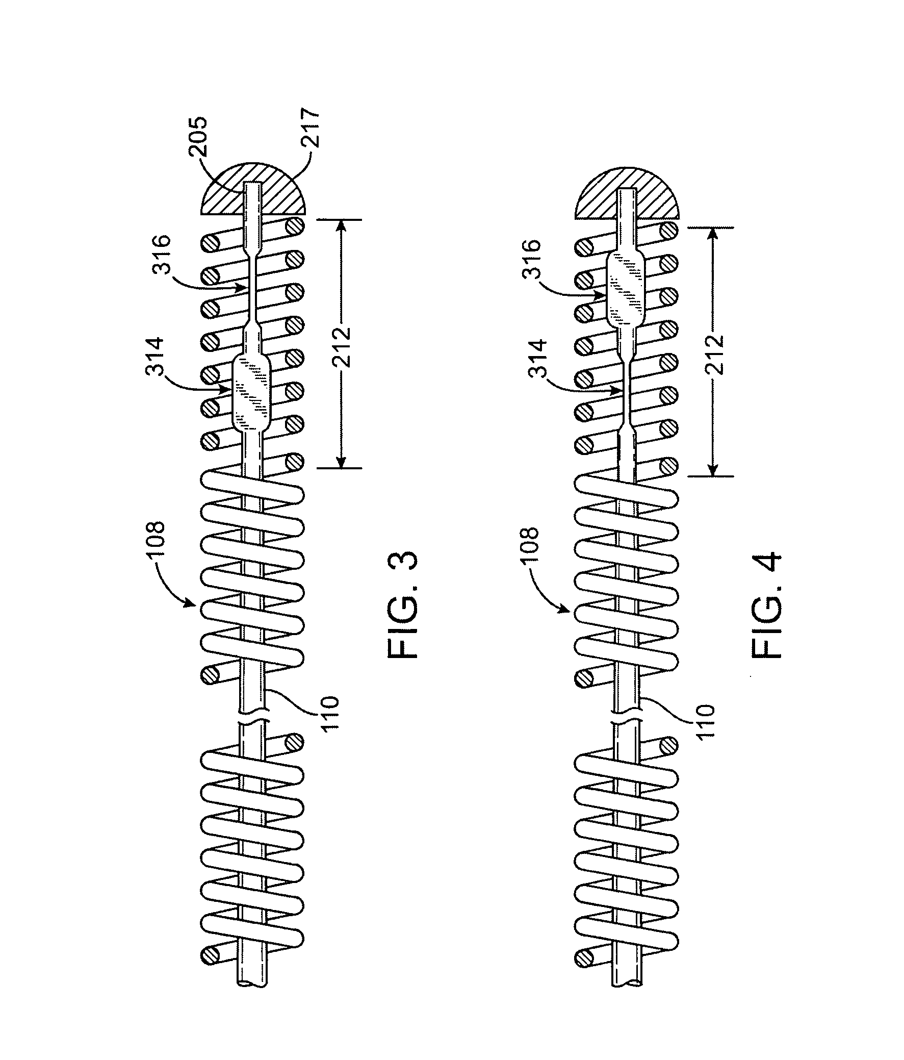
The present invention is an intravascular guidewire for use in guiding a catheter through a body lumen. The guidewire has a reduced-diameter distal region that defines a cylindrical core wire. The core wire has a distal tip segment that includes a proximal flat drop and a distal flat drop, which are separated by a cylindrical linking portion. The guidewire shaft is surrounded by a flexible coil. The guidewire can be a unitary structure or have a tapered core wire distal region. The guidewire can be designed to have a planar surface of the proximal and distal flat drops that are perpendicular to each other or at an angle to each other. The technical effects of the invention include improved maneuverability and better control of the guidewire during use.

Problems solved by technology

Although each of the above-described tip constructions has its advantages, each also presents some compromises and difficulties.
Although the construction in which the core extends fully to, and is attached to the tip weld, i.e., a core-to-tip construction, is particularly suited for crossing a very tight stenosis, it may be unsuitable in those instances where a more tortuous anatomy with a less restrictive stenosis is encountered.
Among the difficulties presented with a ribbon tip construction is that the relatively low bending stiffness of the distal tip sometimes permits the ribbon and the surrounding coil to prolapse, that is, to fold back on itself.

Method used


Image

  • Medical guidewire tip construction
  • Medical guidewire tip construction
  • Medical guidewire tip construction

Examples


Embodiment Construction

[0022] Specific embodiments of the present invention are now described with reference to the figures, wherein like reference numbers indicate identical or functionally similar elements. The terms “distal” and “proximal” are used in the following description with respect to a position or direction relative to the treating clinician. “Distal” or “distally” are a position distant from or in a direction away from the clinician. “Proximal” and “proximally” are a position near or in a direction toward the clinician.

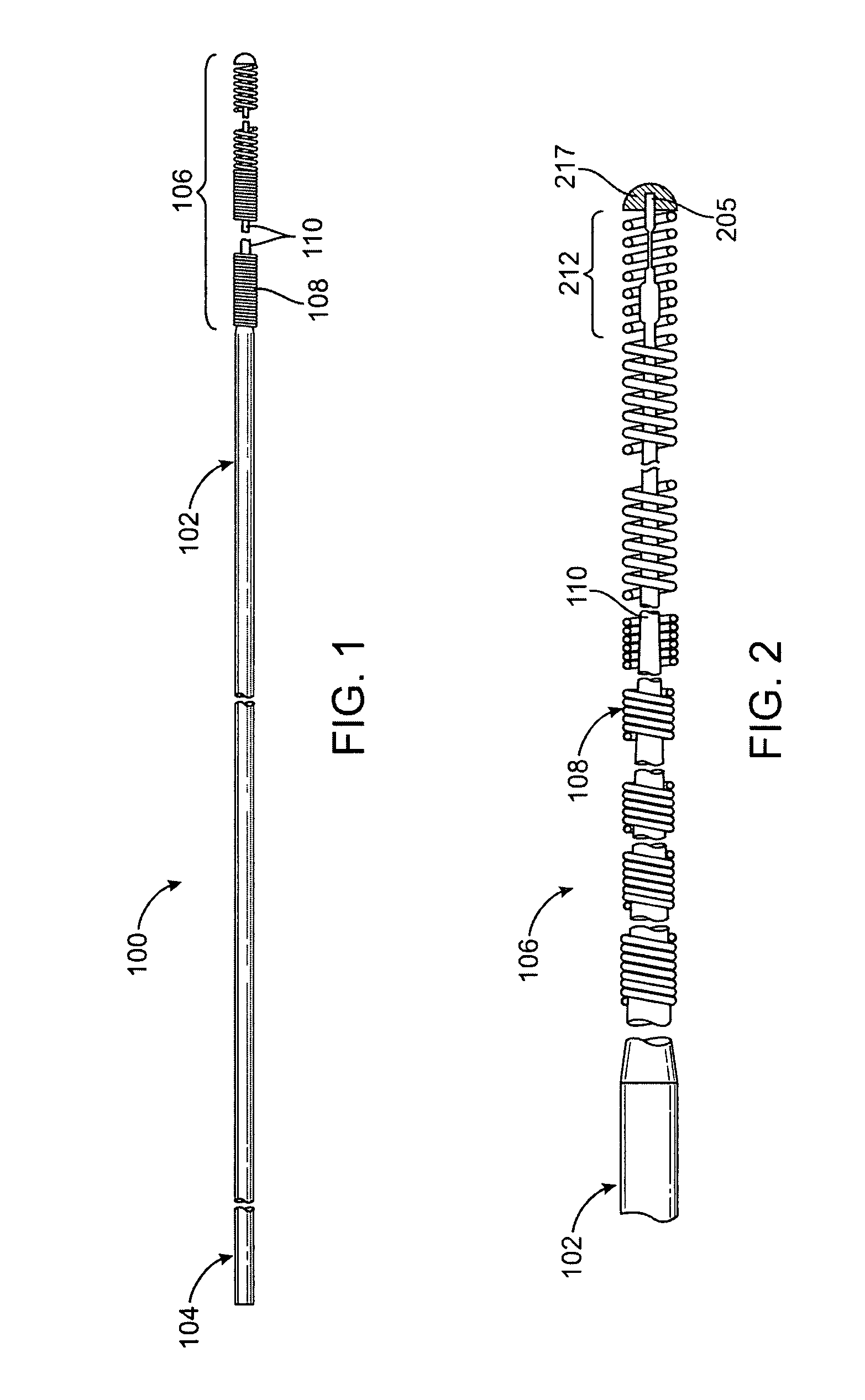
[0023]FIGS. 1 and 2 illustrate a side view of a guidewire 100 in accordance with an embodiment of the present invention. Guidewire 100 includes an elongate shaft 102 formed from an appropriate material, such as stainless steel, nitinol, an alloy of tungsten-rhenium, or, a work-hardenable cobalt chromium superalloy such as 35NLT. Shaft 102 has a proximal end 104, a distal end 205, and a distal region 106. Proximal end 104 of shaft 102 may be provided with a tubular socket (not ...


PUM


Abstract

A medical guidewire having a core-to-tip construction that includes a core wire region surrounded by a flexible coil. The core wire having a distal tip segment that includes a proximal flat drop axially separated from a distal flat drop by a cylindrical or frusto-conical linking portion. The proximal and distal flat drops each having a pair of parallel planar surfaces, wherein the planar surfaces of the proximal flat drop are at an angle to the planar surfaces of the distal flat drop. The tip construction provides improved flexibility while maintaining columnar strength and providing excellent torsional characteristics.

Description

FIELD OF THE INVENTION [0001] The invention relates to medical guidewires used to assist in the placement of catheters in body lumens and, particularly, to an improved tip structure for such guidewires. BACKGROUND OF THE INVENTION [0002] Medical guidewires are used in numerous catheterization procedures as an aid to placement of a catheter at a selected site within a body lumen. The catheter is constructed to perform a particular procedure at that internal site. Among the more common uses of guidewires is in the catheterization of blood vessels for diagnostic or therapeutic purposes. In such a vascular catheterization procedure, the guidewire is inserted, usually percutaneously, into one of the patient's blood vessels and is manipulated and advanced through the branches of the vascular system to the target site. The catheter is then threaded over and advanced along the guidewire, with the guidewire serving to guide the catheter directly to the target site. [0003] A number of cathete...

Claims


Application Information

Patent Timeline
Patent Type & Authority Applications(United States)
IPC IPC(8): A61M25/00
CPCA61M25/0054A61M25/09A61M2025/09083A61M2025/09175
Inventor BIGGINS, JAMES
Owner MEDTRONIC VASCULAR INC
Learn More