
Prevention of high resistance electrical connections

Inactive Publication Date: 2007-10-11
KOPELMAN ROBERT Z
View PDF12 Cites 12 Cited by
  • Summary
  • Abstract
  • Description
  • Claims
  • Application Information

AI Technical Summary

Benefits of technology

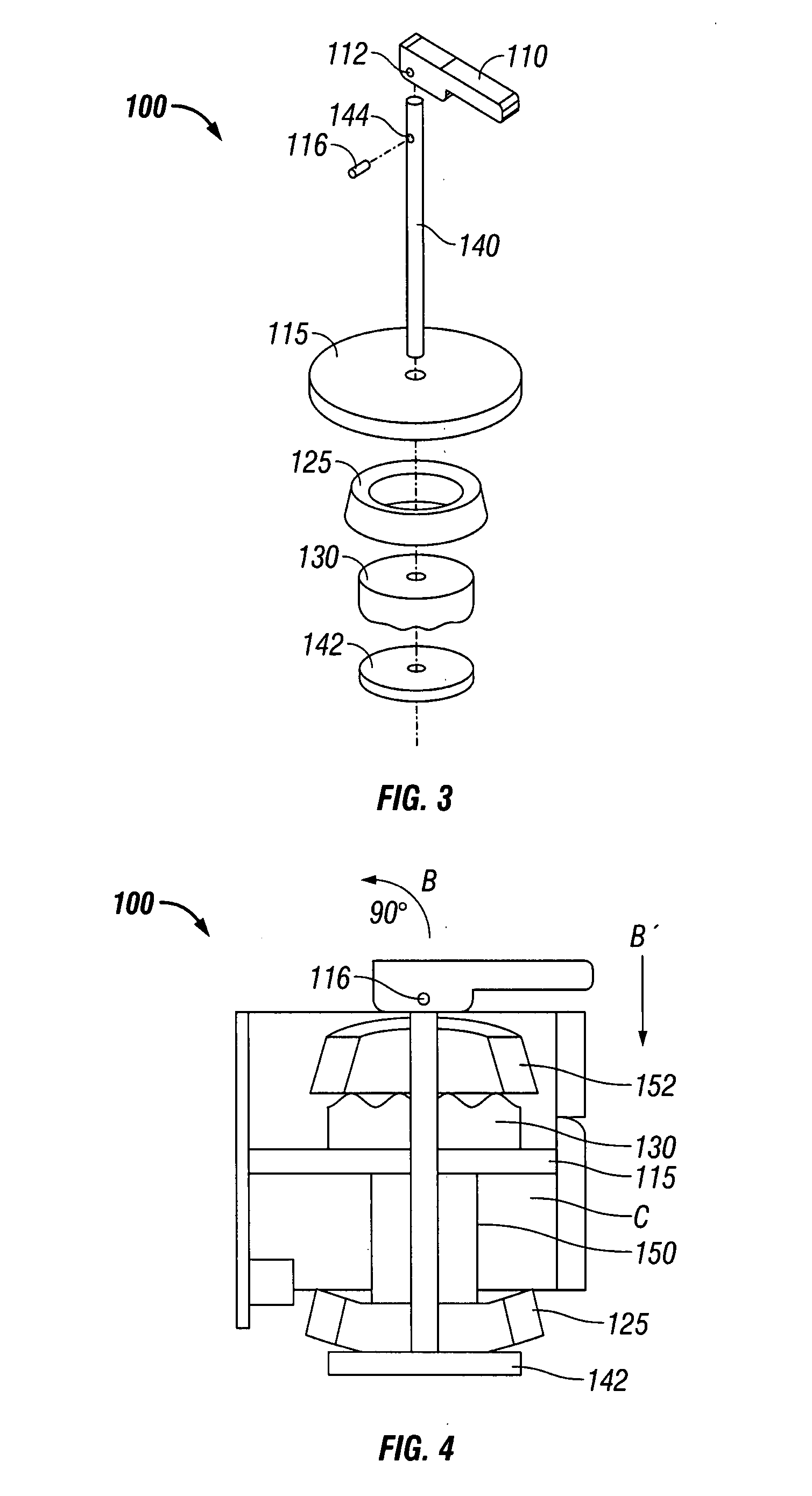
[0010] The present disclosure further relates to a termination assembly for an electrical device such as, for example, a receptacle outlet. The termination assembly is configured to indefinitely retain a conductor such as, for example, copper wire therein to prevent high resistance connections caused by loose connections. In this way, the termination assembly of the present disclosure provides a novel means of preventing high resistance connections not appreciated by conventional termination means. Generally, the termination assembly of the present disclosure includes a spring component, a shaft, a handle, a pin member, at least one compression plate, and a terminal shaft including a terminal head defined thereon. Various material including, for example, conductor wire may be placed between two of the one or more compression plates which are subsequently compressed by operation of the handle and / or terminal head in conjunction with the pin member and spring component to indefinitely retain the conductor wire therein.
[0011] Additionally, the present disclosure relates to preventing high resistance connections within a receptacle outlet caused by loose connections associated with male-prong to female-receptacle connections involving plug connectors by indefinitely maintaining the integrity of such connections.

Problems solved by technology

However, these methods are limited to merely addressing the problem of overheating conditions once the condition has already occurred rather than preventing the condition from occurring in the first place.
Common causes of high resistance connections include loosening of the terminations due to extraneous vibrations as well as expansion and contraction of the termination point and / or the screw terminal.
A glowing connection is a high resistance connection, which can form at the interface of a copper wire and a screw terminal, for example, a receptacle, resulting in a fire.

Method used


Image

  • Prevention of high resistance electrical connections
  • Prevention of high resistance electrical connections
  • Prevention of high resistance electrical connections

Examples


Embodiment Construction

[0017] Particular embodiments of the present disclosure are described hereinbelow with reference to the accompanying drawings. In the following description, well-known functions or constructions are not described in detail to avoid obscuring the present disclosure in unnecessary detail.

[0018] The present disclosure relates to a system and method for preventing high resistance connections associated with electrical devices such as, for example, receptacles, by securing permanent and safe termination of electrical connections, e.g., termination connections, male-prong to female-receptacle connections.

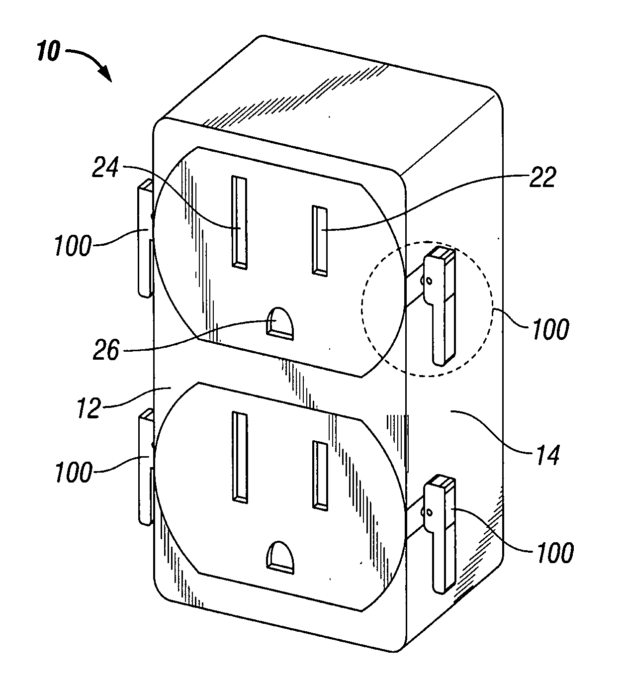
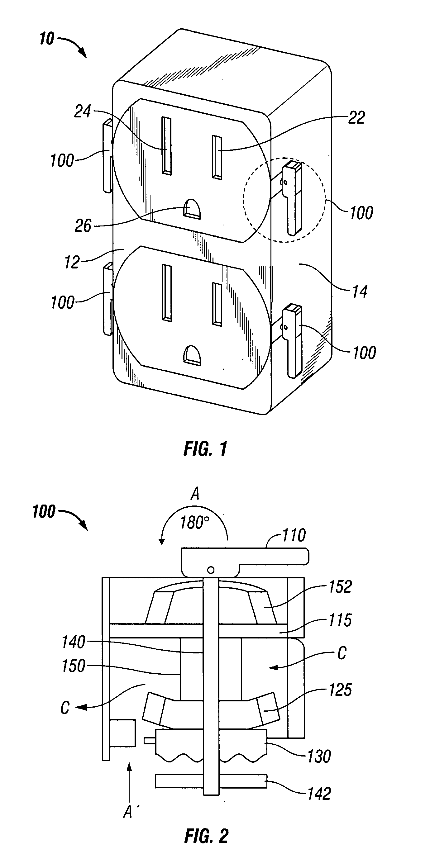
[0019] Referring initially to FIG. 1, an electrical device such as a receptacle 10 is shown. The receptacle 10 includes a base cover 12 secured in mated relation to a base 14. Base cover 12 may be secured to base 14 via fasteners (not shown) such as mating via ultrasonic heating, screws, clips, etc. Base cover 12 may be formed of any material which inherently provides high temperature s...


PUM


Abstract

A terminal assembly for a device configured to indefinitely retain material therein includes a terminal shaft having a terminal head defined on an end thereof and at least one shaft including a handle and a pin member defined at opposed ends thereof. The handle includes a cam surface configured to bias the terminal head upon operation of the handle, thereby causing the pin to bias at least one compression plate within a compression area defined between the handle and the pin. The handle is configured to operate in a first position wherein the at least one compression plate is biased towards the compression area and a second position wherein the at least one compression plate is retracted from the compression area. The assembly further includes a spring component configured to retain the at least one compression plate within the compression area, wherein the material is retained within the compression area.

Description

[0001] This application claims priority from Provisional Patent Application Ser. No. 60 / 786,726 filed on Mar. 28, 2006 entitled “Prevention of High Resistance Electrical Connections,” the entire contents of which are incorporated herein by reference. [0002] This application also claims priority from Provisional Patent Application Ser. No. 60 / 786,725 filed on Apr. 17, 2006 entitled “Electrical Fire Prevention from over Temperature Conditions,” the entire contents of which are incorporated herein by reference.BACKGROUND [0003] 1. Technical Field [0004] The present disclosure relates to electrical devices, systems and methods. More particularly, the present disclosure is directed to electrical devices such as, for example, receptacles including termination terminals, for electrical conductors, such as copper wiring. [0005] 2. Background of Related Art [0006] The technology of the present disclosure is designed to prevent fires caused by high resistance connections in electrical devices...

Claims


Application Information

Patent Timeline
IPC IPC(8): H01R13/58
CPCH01H37/74H01R13/639H01R2103/00H01R24/78H01R13/6395
Inventor KOPELMAN, ROBERT Z.
Owner KOPELMAN ROBERT Z
Learn More