
Palletizing apparatus

a technology of palletizing and spherical plates, which is applied in the directions of packaging, packaging, and packaging of items, can solve the problems of undesired damage to the pallet, undesired damage to the articles or their packaging, and the apparatus was susceptible to damage, etc., and achieves the effect of convenient configuration and operation, and facilitate us

Inactive Publication Date: 2007-10-11
REICHEL & DREWS
View PDF6 Cites 12 Cited by
  • Summary
  • Abstract
  • Description
  • Claims
  • Application Information

AI Technical Summary

Benefits of technology

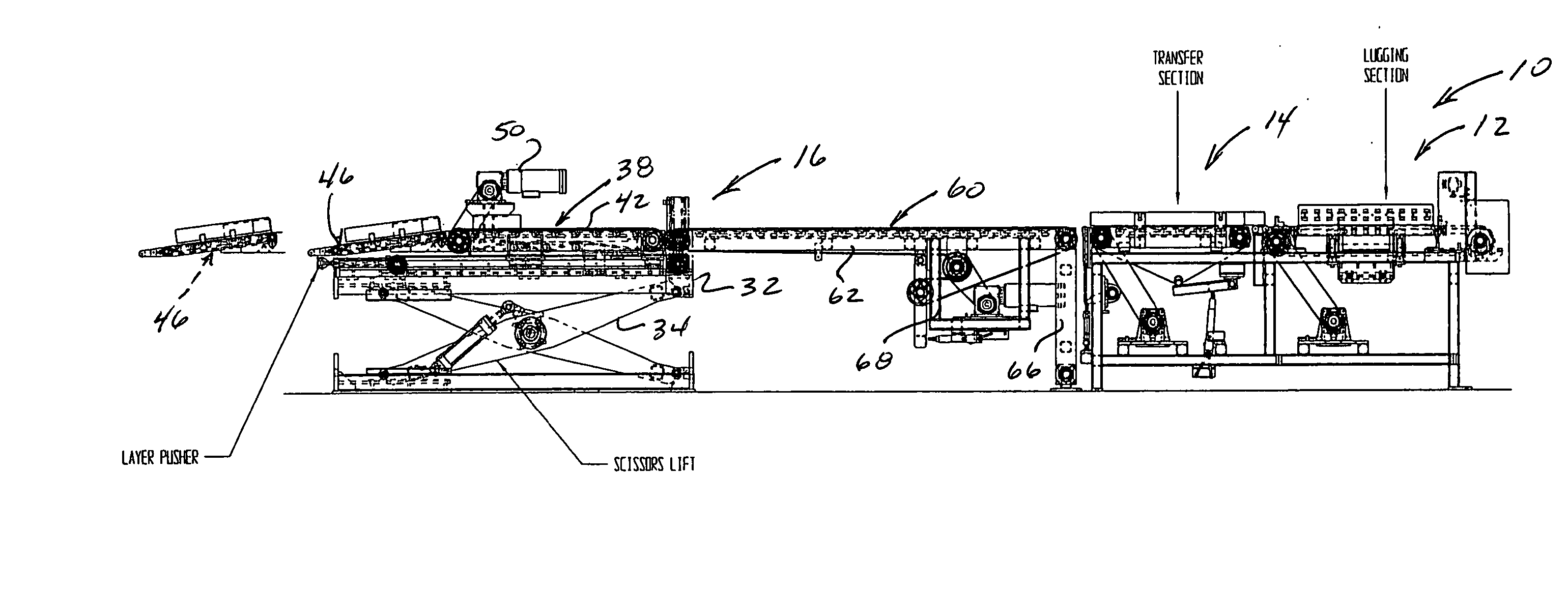
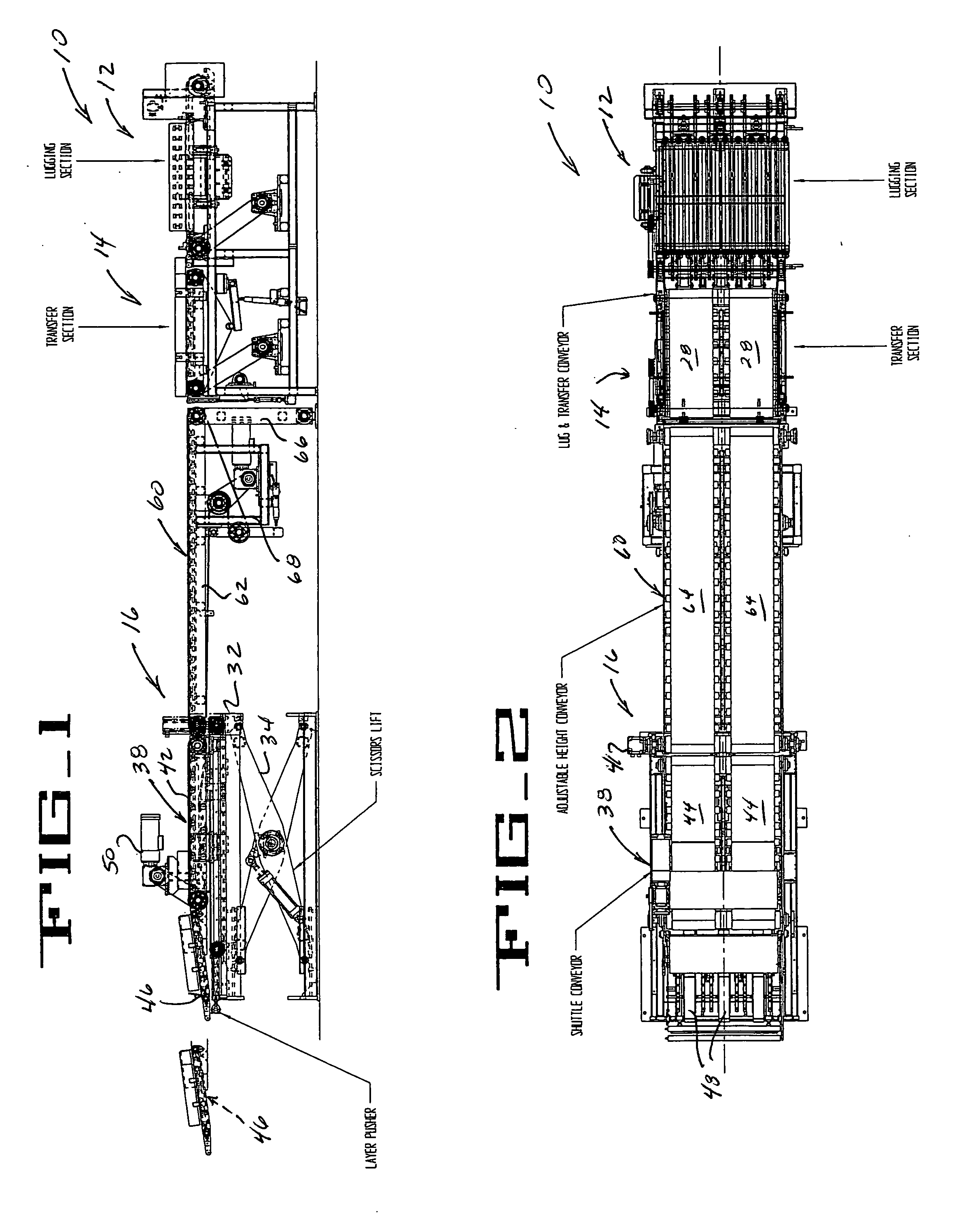
[0009] The present invention is directed to a palletizing apparatus which comprises a system of selectively operable conveyors which act in cooperation with each other to successively transfer groups of articles onto an associated shipping pallet, with each group of articles generally corresponding to one layer on the associated pallet. The apparatus includes a vertically adjustable shuttle conveyor from which each group of articles is transferred onto the associated pallet, after the shuttle conveyor is appropriately vertically positioned so that each group of articles can be stacked upon a previously placed group of articles. Features of the present palletizing apparatus particularly facilitate use with relatively heavy articles, such as bundled stacks of asphalt roofing shingles, but it will be recognized that an apparatus embodying the principles disclosed herein can be readily configured and operated for handling and palletizing a wide variety of different articles.
[0013] To facilitate “squaring” of each group of articles on the associated pallet, the present apparatus includes a layer pusher mounted on the vertically adjustable frame of the shuttle conveyor apparatus for engaging and pushing one of the groups of articles after movement of the articles onto the pallet from the shuttle conveyor. Notably, the layer pusher is movable independently of the reciprocable movement of the shuttle conveyor by mounting of the layer pusher on the vertically adjustable frame upon which the shuttle conveyor is reciprocably mounted. The present apparatus preferably includes a pair of pneumatically operated fluid cylinders to effect movement of the layer pusher so that the pushing force can be adjusted, depending upon the size of the article, its weight, packaging material, etc., to push with as much or as little force as may be required, thus effecting layer “squaring” in a manner which promotes product integrity, while avoiding any shock loading to the drive system which reciprocates the shuttle conveyor.
[0014] In accordance with the present invention, the shuttle conveyor includes articulable upstream and downstream conveyor sections, with each group of articles first received on the upstream section from the transfer conveyor of the apparatus, and thereafter conveyed by the downstream section as each group is moved off of the shuttle conveyor and onto the associated pallet. Notably, the downstream section of the shuttle conveyor is mounted for pivotal movement relative to the upstream section about a horizontal pivot axis. This downstream section of the shuttle conveyor, sometimes referred to as the nose section, thus is desirably provided with a “flip-up” feature. By this arrangement, any inadvertent contact between the shuttle conveyor, when in its extended position, and the articles previously stacked on the pallet, minimizes any damage to the articles and the shuttle conveyor itself, as the nose or downstream section of the shuttle conveyor is permitted to pivot upwardly if such contact should occur.
[0016] Efficient handling of articles is further facilitated by providing the transfer conveyor of the present palletizing apparatus with a selectively operable servo drive, whereby the transfer layer can be started and stopped for intermittently receiving and advancing each group of articles carried by the transfer conveyor. As will be appreciated, this desirably avoids impact loading of mechanical stop elements or the like, and desirably avoids damage to the articles, or their packaging, which can occur in arrangements where the articles are stopped against a mechanical stop element, but an associated conveyor belt continues to run.

Problems solved by technology

While this previous arrangement effected the desired intermittent advancement of each group of articles, the apparatus was susceptible to damage attendant to impact loading of the stop elements as the articles of each group are advanced into position against the stop elements.
Additionally, the continuously running belts could undesirably mar or damage the articles or their packaging as the articles are held in position against the retractable stop elements.
However, in this previous arrangement, the cantilevered portion of the shuttle conveyor was mounted in fixed relationship to the conveyor support frame, and thus could undesirably damage articles on the pallet, or damage the apparatus itself, if the shuttle conveyor was inadvertently lowered in its extended, cantilevered orientation.
However, this bumper element could not be moved independently of the shuttle conveyor, detracting from its efficient operation, since the previously-stacked group of articles might be insufficiently moved for proper “squaring” on the pallet, or moved beyond the desired “squared” orientation.
Excessive engagement of the bumper with the stacked group of articles could not only cause undesired damage to the articles, but could also create undesirable impact loads in the shuttle conveyor apparatus.
This sliding action was found to be subject to significant wear in the previous apparatus.

Method used


Image

  • Palletizing apparatus
  • Palletizing apparatus
  • Palletizing apparatus

Examples


Embodiment Construction

[0025] While the present invention is susceptible to embodiment in various forms, there is shown in the drawings, and will hereinafter be described, presently preferred embodiments, with the understanding that the present disclosure is to be considered as an exemplification of the invention, and is not intended to limit the invention to the specific embodiment illustrated.

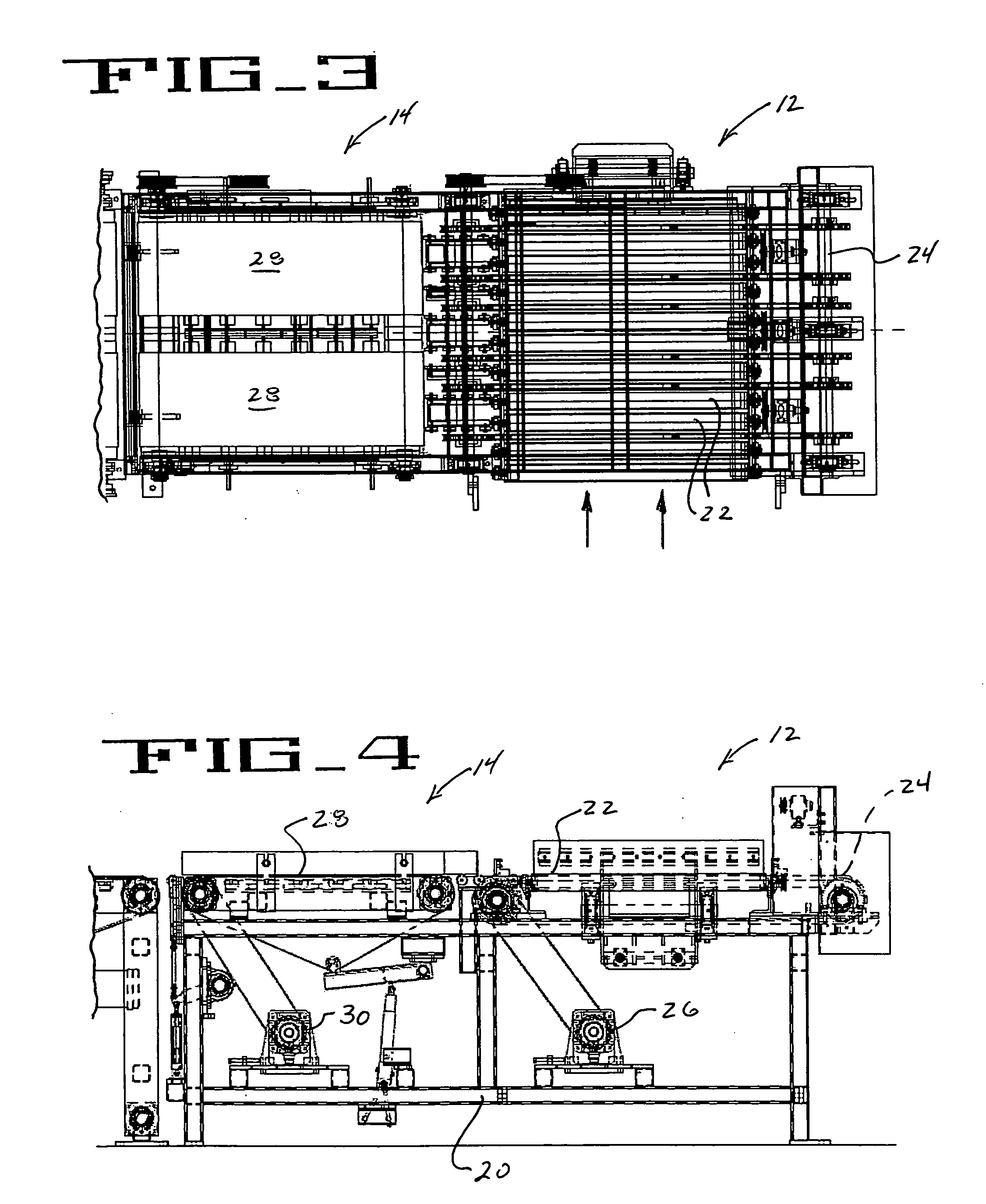
[0026] With reference now to FIGS. 1 and 2, therein is illustrated a palletizing apparatus 10 embodying the principles of the present invention. As will be further described, the apparatus 10 comprises a system of cooperating conveyor devices which act together to facilitate assembly of groups of articles for subsequent transfer and placement upon an associated shipping pallet, with each group of articles stacked upon the previous group on the pallet. While the present invention is particularly suited for handling and palletizing relatively heavy articles, such as bundled stacks of asphalt roofing shingles, it wil...


PUM


Abstract

A palletizing apparatus is configured to assemble groups of articles, and successively transfer the groups onto an associated pallet. The apparatus includes lugging and transfer sections where the groups of articles are assembled, and thereafter transferred to a vertically adjustable shuttle conveyor apparatus. The shuttle conveyor apparatus includes a horizontally reciprocable shuttle conveyor, which can move from a first, retracted position, to a second, extended position. During retraction of the shuttle conveyor from its second position to its first position, the conveyor is operated so that each group of articles is transferred therefrom onto the associated pallet. Features of the present apparatus facilitate its efficient and consistent operation, while avoiding excessive wear of the apparatus.

Description

TECHNICAL FIELD [0001] The present invention relates generally to an apparatus for successively positioning groups of articles in layers on an associated pallet, and more particularly to a palletizing apparatus configured to facilitate efficient, accurate positioning of groups of relatively heavy articles, which may comprise bundles of asphalt roofing shingles, while avoiding damage to the articles themselves, and excessive wear to the apparatus. BACKGROUND OF THE INVENTION [0002] Attendant to shipment and storage of various articles, it is common for such articles to be arranged in layers on an associated pallet to facilitate handling of the articles by a forklift or other piece of equipment. While a variety of different palletizing apparatus are known, heretofore, handling and palletizing of relatively heavy articles, such as bundles of asphalt roofing shingles, has required use of specialized palletizing equipment. [0003] In one known palletizing apparatus for handling bundles of...

Claims


Application Information

Patent Timeline
IPC IPC(8): B65G57/22
CPCB65G57/24B65G57/112
Inventor DOMENZ, THOMAS B.
Owner REICHEL & DREWS
Learn More