Optical disc drive

Inactive Publication Date: 2007-10-04
HITACHI CONSUMER ELECTRONICS CORP +1
View PDF10 Cites 2 Cited by
  • Summary
  • Abstract
  • Description
  • Claims
  • Application Information

AI Technical Summary

Benefits of technology

[0012]The technique described in the patent document 1 has a structure to absorb the reaction of the impact force applied when the optical head is moved to the outer circumference position of the disc and the impact force caused by a shaft vibration of a warm gear serving as a guide mechanism or the like, and it is intended to buffer the radial impact force. The technique described in the patent document 2 is designed such that a first buffering member is mounted in the inner circumference of the guide member so that when a supporting member supporting the optical head is moved in the disc radial direction, the first buffering member buffers the collision of the optical head supporter with the inner circumference and outer circumference and a second buffering member is mounted in a chassis portion to which the optical head is brought into contact with the outer circumference, so that the impact in the disc radial direction is consequently buffered. The technique described in the patent document 3 is designed such that the bearing of the carriage on which the optical head is mounted is restrained by the stopper which is driven to be raised and lowered by the electromagnetic solenoid through the link mechanism, and when the impact force is applied, the movement of the optical head in the disc radial direction is prevented, thereby avoiding the collision with the other parts.
[0014]The present invention is proposed in view of such environments. Therefore, it is an object of the present invention to provide a thin optical disc drive whose impact resistance performance is improved.
[0018]As mentioned above, according to the present invention, the thin optical disc drive having a structure for preventing the damage to the inner parts caused by the impact and the like is provided.

Problems solved by technology

Thus, by the examples of the impact force buffering structure to the disc radial direction movement of the optical head disclosed in the patent documents 1 to 3, it is difficult to improve the impact force absorption effect of the thin optical disc drive.

Method used


Image

  • Optical disc drive
  • Optical disc drive
  • Optical disc drive

Examples


Embodiment Construction

[0027]The best mode of carrying out an optical disc drive of the present invention will be described below with reference to the attached drawings. FIGS. 1 to 8B are views exemplifying the embodiments of the present invention. In those drawings, the portion to which the same symbol is assigned indicates the same member, and its basic configuration and operation are assumed to be similar.

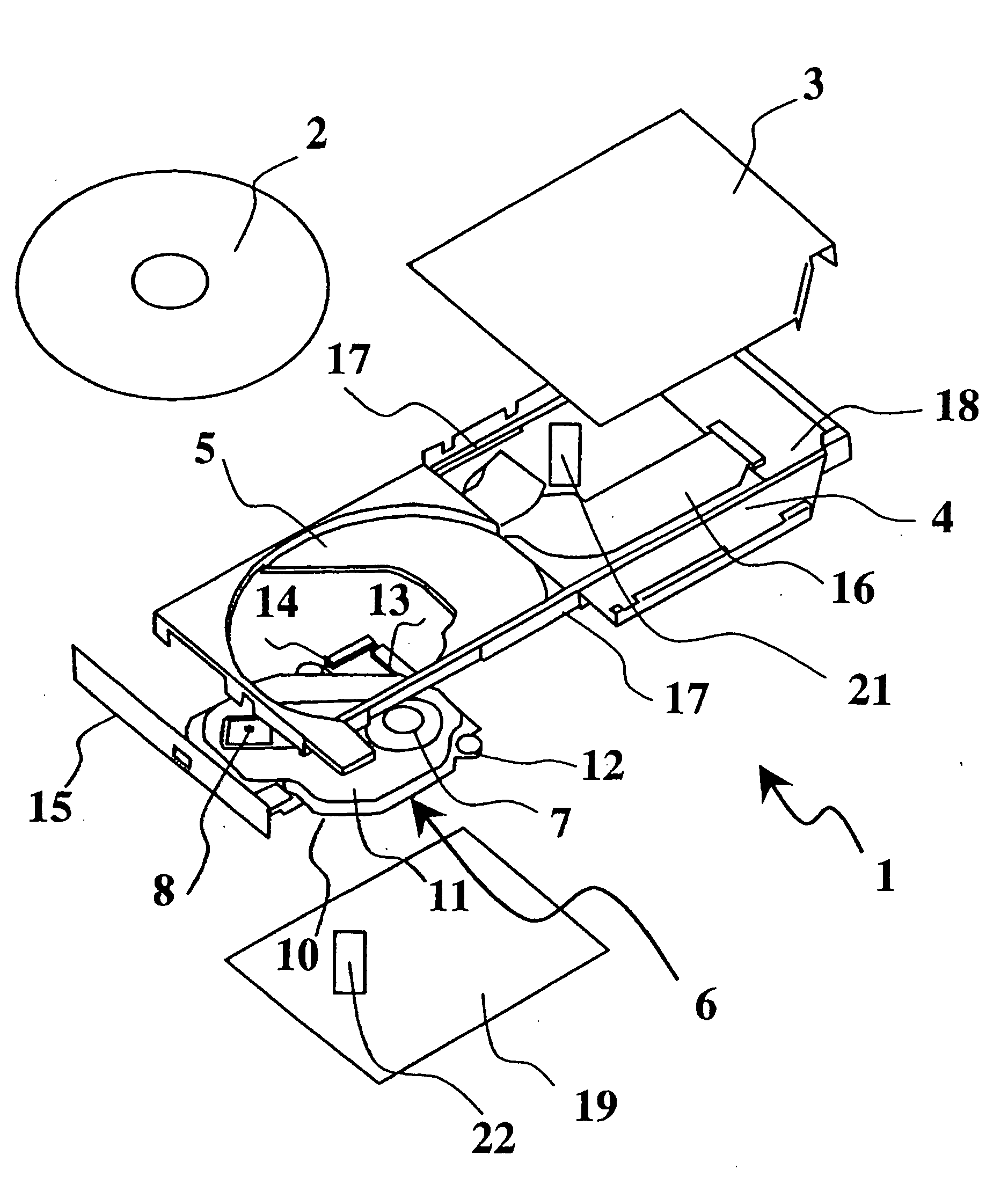
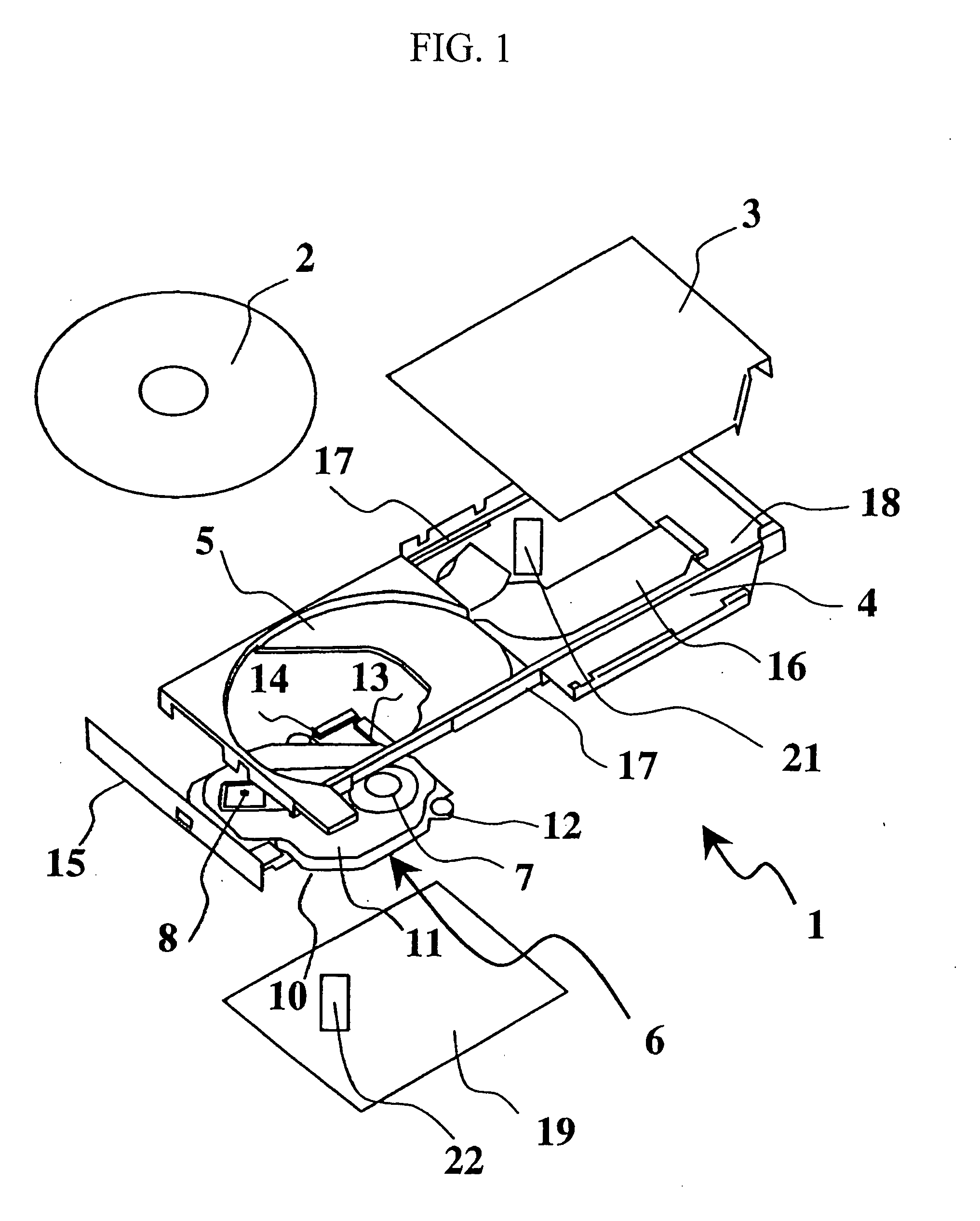
[0028]At first, the configuration of the optical disc drive according to one embodiment of the present invention is explained. FIG. 1 is an exploded perspective view of the optical disc drive and recording medium according to the present embodiment. An optical disc drive 1 records information to a record surface of a disc 2 and replays it from a record surface of a disc 2. The disc 2 is CD, DVD, BD (Blue Ray Disc) or the like that has a diameter of 120 mm and a thickness of 1.2 mm as its dimension.

[0029]As shown in FIG. 1, the optical disc drive 1 has a casing which is made by a top cover 3 and a bot...


PUM


Abstract

The present invention provides a thin optical disc drive whose impact resistance performance is improved.An under cover 19 is provided with a collision evasion hole 21 at a position corresponding to an end of an optical head housing 25. Moreover, a bottom cover 4 is provided with an impact force buffering member 22 at a position corresponding to the collision evasion hole. When an impact force acts on an optical disc drive 1, the impact force to the optical head housing 25 is buffered by the structure. Consequently, it is possible to prevent the optical head 8 from being damaged, and it is possible to improve the reliability of the optical disc drive 1.

Description

BACKGROUND OF THE INVENTION[0001]1. Field of the Invention[0002]The present invention relates to a thin optical disc drive that is referred to as a slim drive, and more particularly relates to an optical disc drive that has a mechanism for preventing damage to inner parts caused by an impact and the like.[0003]2. Description of the Related Art[0004]In an optical disc drive for CD, DVD and the like, which is installed in a laptop personal computer and the like, its structure becomes slimmer, and a slim drive having a thickness of 9.5 mm has been mainly used instead of a currently used drive having a thickness of 12.7 mm. Such a thin optical disc drive has a narrow inner space, and therefore, a collision between inner parts caused by an impact is apt to occur. Thus, there is a fear that the damage to parts causes the deterioration in the reliability performance of the optical disc drive. In particular, in an optical head, which is a main part inside the optical disc drive, its support...

Claims


Application Information

Patent Timeline
IPC IPC(8): G11B17/03
CPCG11B17/051
Inventor YAMAUCHI, YOSHIAKIYAMAGISHI, HIROSHIKIMURA, KUNIYUKITSUBOTA, SHIYAUCHIGIRI, TATSUMI
Owner HITACHI CONSUMER ELECTRONICS CORP
Why Eureka
Try Eureka