
Rod contouring apparatus and method for percutaneous pedicle screw extension

Active Publication Date: 2007-10-04
STRYKER EURO OPERATIONS HLDG LLC
View PDF99 Cites 185 Cited by
  • Summary
  • Abstract
  • Description
  • Claims
  • Application Information

AI Technical Summary

Benefits of technology

[0017]In another aspect, the invention performs a function similar to a surgical navigation system with simple manual instruments that create a mechanical analog of the body target sites outside the body. This invention further provides a convenient template for the shaping of an implantable device to mate with target body sites without requiring a full surgical exposure to access the target body sites. This invention also provides a suitable level of positional control of the template to allow the surgeon discretion in positioning the template and shaping the implantable device.

Problems solved by technology

These procedures result in extensive tissue traumatization and consequently in prolonged recovery time, risk of infections, high hospitalization costs, pain that can be more severe than the pain due to the initial ailment, and in some cases permanent scarring.
The avoidance of general anesthesia reduces post-operative recovery time and the risk of complications.
Minimally invasive surgical procedures are especially desirable for spine surgeries because spine pathologies are located deep within the body without clear muscle planes and there is danger of damaging the adjacent neural and vascular tissues.
The destruction to the spinal structures is even more extensive during fusion procedures, which require more lateral tissue dissection and exposure to access the transverse processes and pedicles for placement of pedicle screws, rod constructs for stability, and bone graft under direct vision.
Placement of these connecting elements requires open surgery, which is currently one of the major limitations of other percutaneous cannula access methodologies.
This is not feasible in minimally invasive surgical procedures because the surgeon has neither the physical access nor visibility required to test and adjust the device in situ.
Unfortunately, if a larger incision must be made to permit bone measurement and implant selection or configuration, most of the beneficial effects of the MIS implantation procedure will be lost.

Method used


Image

  • Rod contouring apparatus and method for percutaneous pedicle screw extension
  • Rod contouring apparatus and method for percutaneous pedicle screw extension
  • Rod contouring apparatus and method for percutaneous pedicle screw extension

Examples


Embodiment Construction

[0042]In this application, an “anatomic point” is a location within the body. An anatomic point need not be located on any specific anatomic structure. When applied to anatomy, “proximal” refers to a position relatively closer to the center of the body, and “distal” refers to a position relatively further from the center of the body. However, when referred to a tool or similar implement, “proximal” refers to a portion relatively nearer the operator of the tool or similar implement, and “distal” refers to a portion relatively further from the operator.

[0043]The phrasespatial transformation” refers to any mathematical procedure in which one or more coordinates can be transformed in a manner that permits the original coordinates to be determined based on the results of the transformation. Accordingly, a spatial transformation may involve any combination of translation and rotation of the original coordinates, as long as the transformation can be analytically reversed to permit the or...


PUM


Abstract

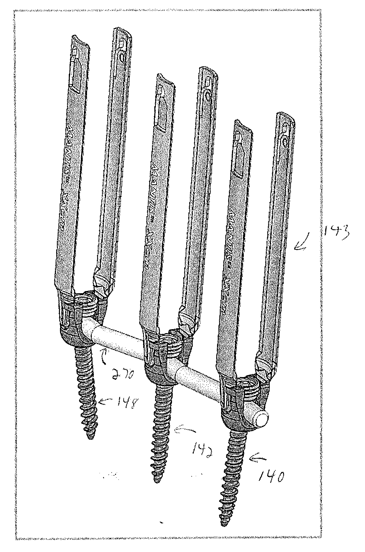
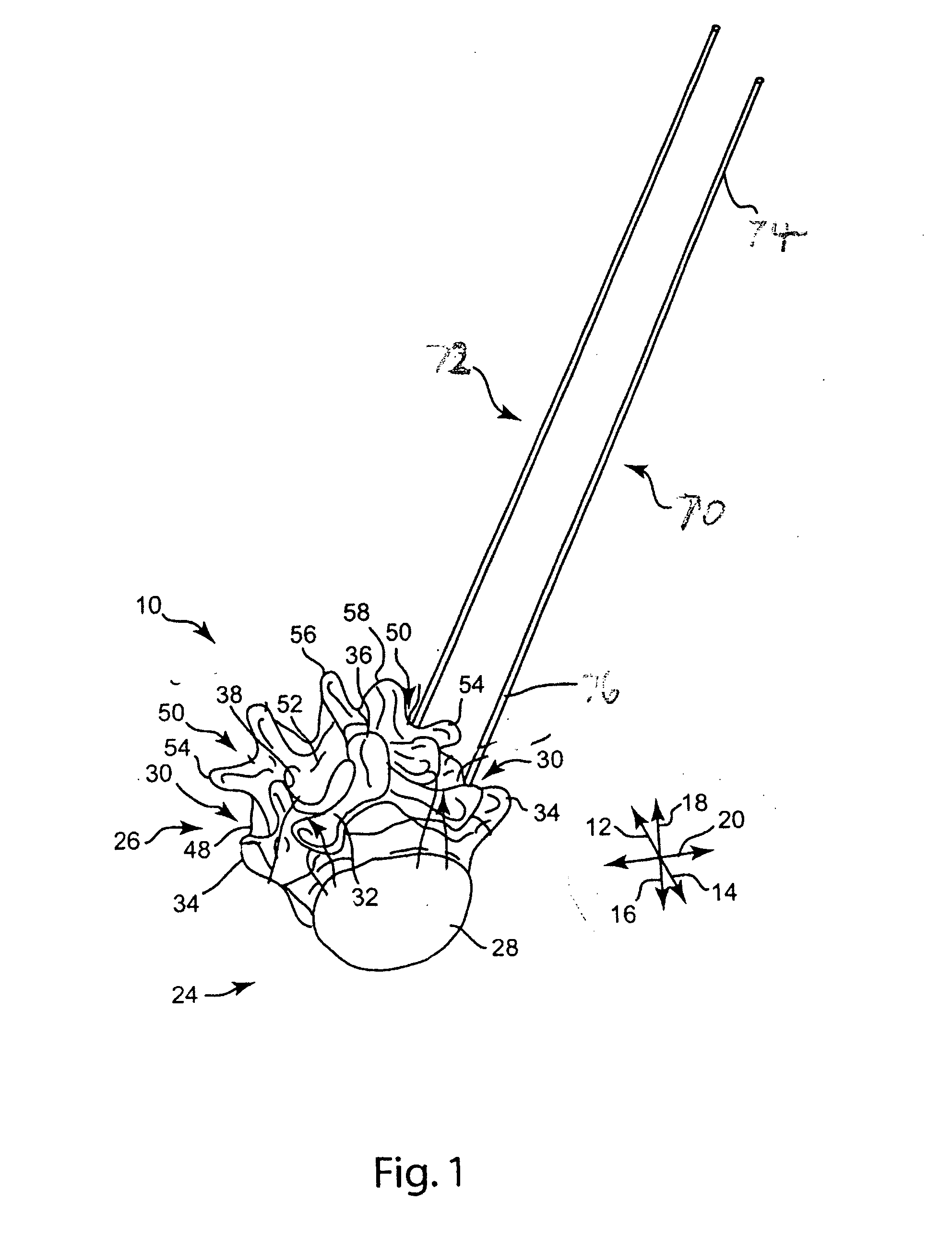
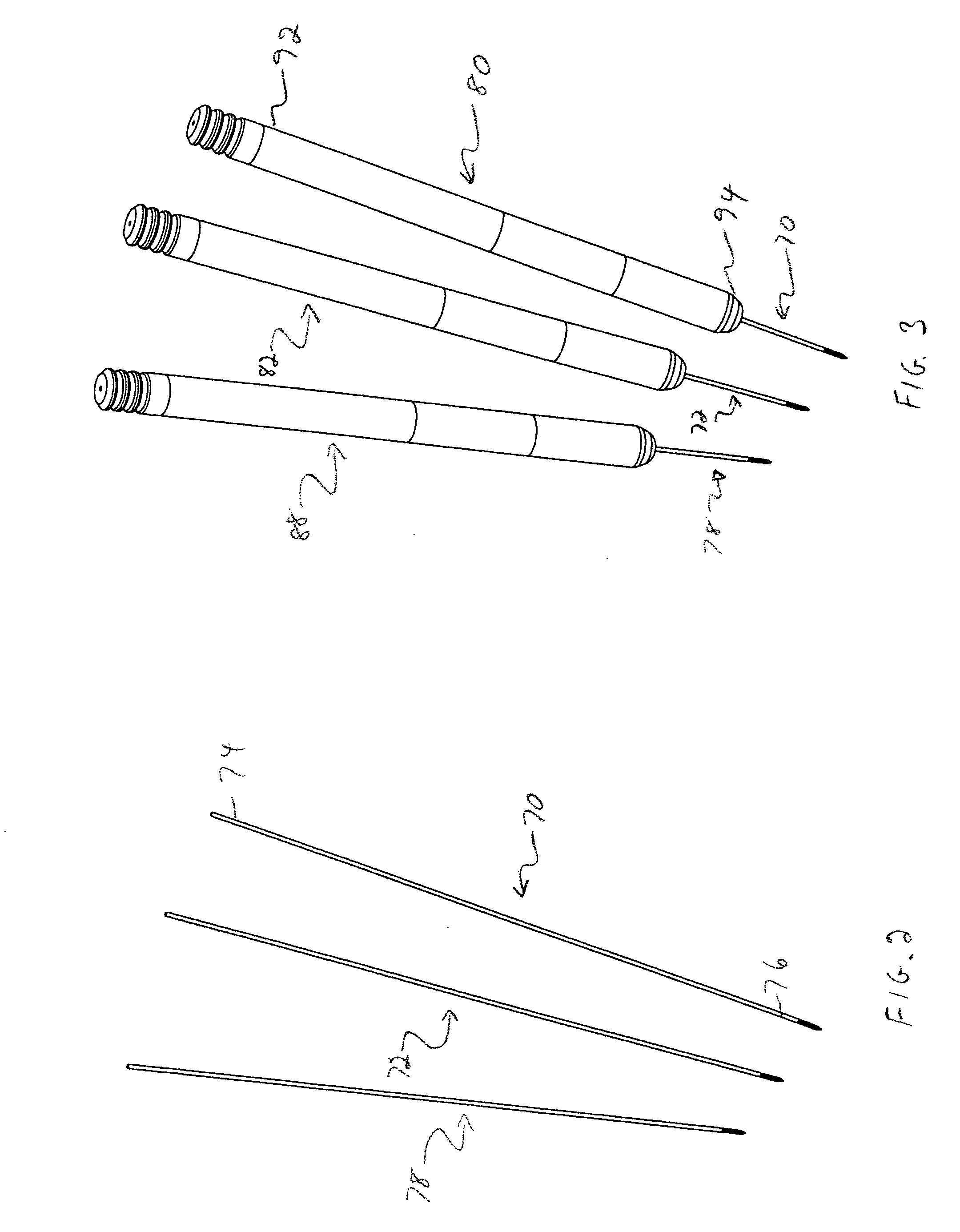
Anatomic points within the body are projected outside the body through the use of extenders (180, 182, 188). The projected points may then be used for measurement, or to facilitate the selection or configuration of an implant that is positioned proximate the anatomic points using a slotted cannula (143). Such an implant may be a rod (270) for a posterior spinal fusion system. Pedicle screws (140, 142, 148) may be implanted into pedicles of the spine, and may then serve as anchors for the extenders. The extenders (180, 182, 188) may have rod interfaces (214, 216, 218) that receive the rod (270) in a manner that mimics the geometry of the pedicle screws (140, 142, 148) so that the selected or configured contoured rod (270) will properly fit into engagement with the pedicle screws (140, 142, 148).

Description

CROSS-REFERENCE TO RELATED APPLICATIONS[0001]This application claims the benefit of the filing date of U.S. Provisional Application No. 60 / 765,606, filed Feb. 6, 2006, and entitled ROD CONTOURING APPARATUS AND METHOD FOR A PERCUTANEOUS PEDICLE SCREW EXTENSIONS, the disclosure of which is hereby incorporated herein by reference.[0002]This application relates to U.S. application Ser. No. 10 / 868,075, entitled “Methods and Devices For Improving Percutaneous Access In Minimally Invasive Surgeries” and filed on Jun. 15, 2004, U.S. application Ser. No. 11 / 178,035, entitled “System and Method For Orthopedic Implant Configuration” and filed on Jul. 8, 2005, and U.S. application Ser. No. 11 / 202,487, entitled “System and Method For Percutaneous Spinal Access” and filed on Aug. 12, 2005, and International Application No. PCT / US2004 / 036640 and filed on Nov. 4, 2004, the disclosures of which are incorporated herein by reference.BACKGROUND OF THE INVENTION[0003]The present invention relates to met...

Claims


Application Information

Patent Timeline
IPC IPC(8): A61F2/30
CPCA61B17/7085A61B17/8863A61B17/7041A61B17/7037A61B17/88A61B17/8897A61B17/7032A61B90/06A61B2090/061A61B17/0218A61B17/7002
Inventor FALLIN, T. WADEBUTTERS, JOSHUA A.
Owner STRYKER EURO OPERATIONS HLDG LLC
Learn More