
Method for joining planar sheets and sheets therefor

a technology of planar sheets and sheets, applied in the direction of mechanical equipment, ropes and cables for vehicles/pulleys, manufacturing tools, etc., can solve the problems of increasing the number of parts required to create a structure, increasing the time, labor and/or cost involved in creating the structure, and general mechanical fasteners

Inactive Publication Date: 2007-10-04
IND ORIGAMI INC CA US
View PDF16 Cites 17 Cited by
  • Summary
  • Abstract
  • Description
  • Claims
  • Application Information

AI Technical Summary

Benefits of technology

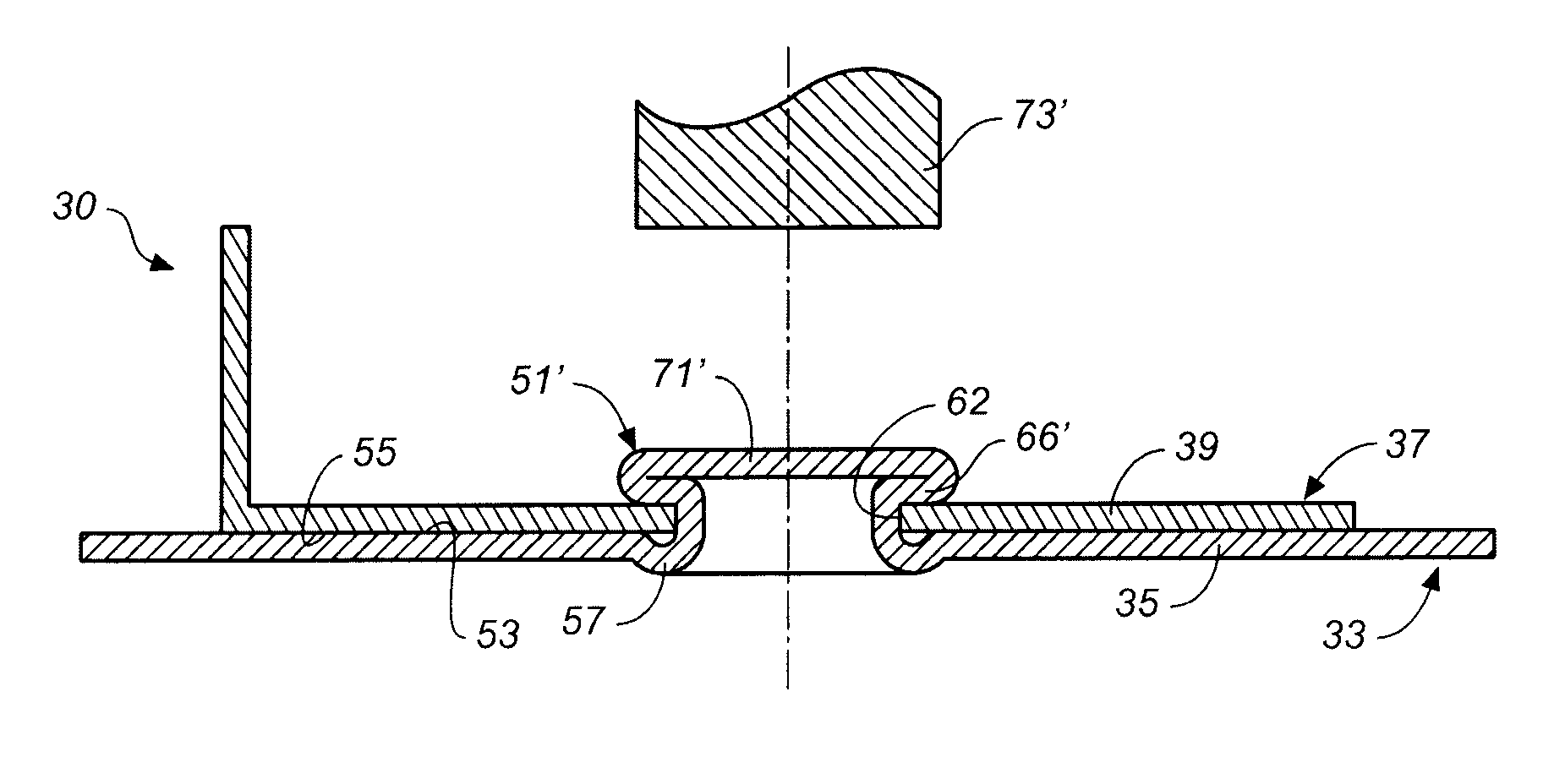
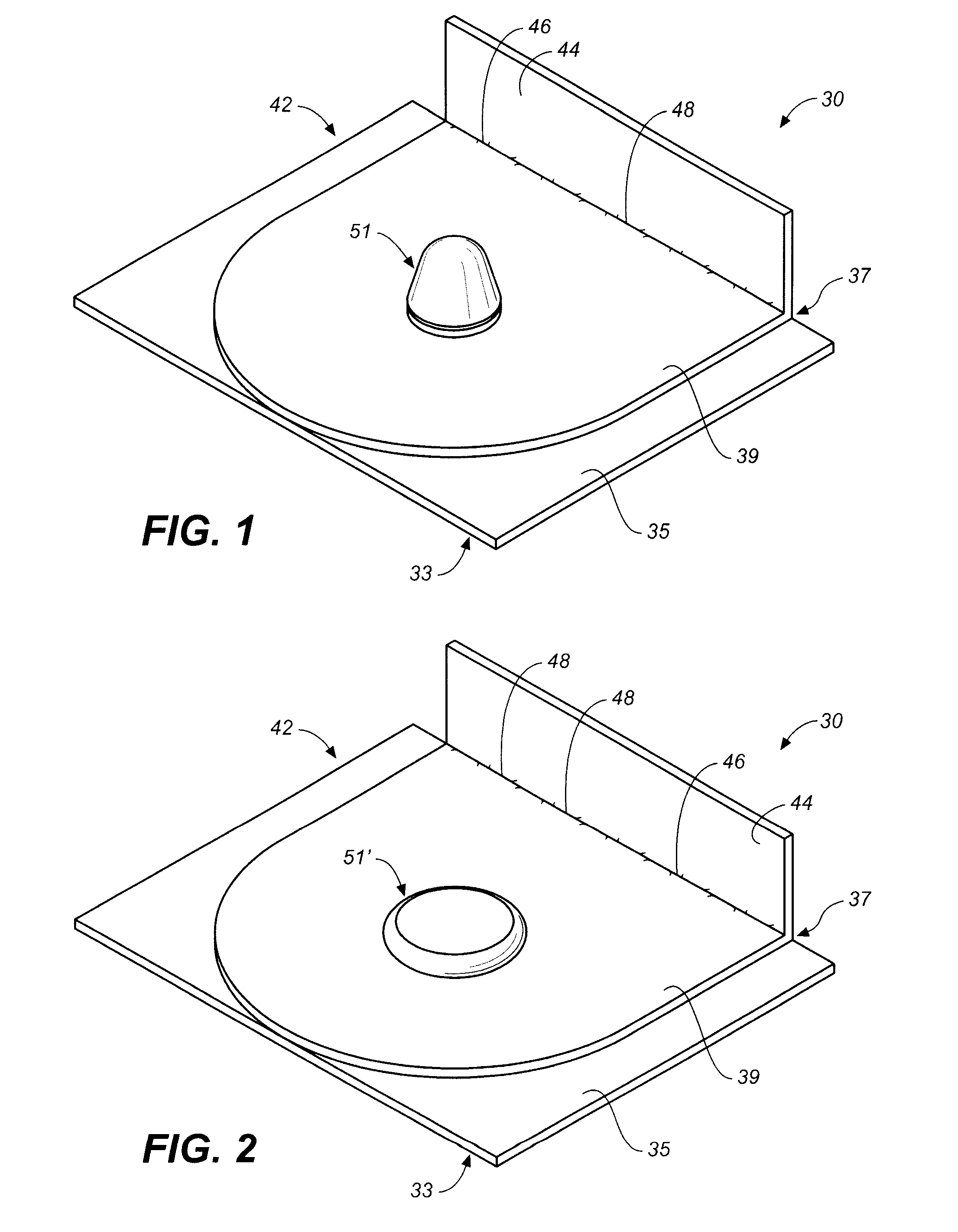
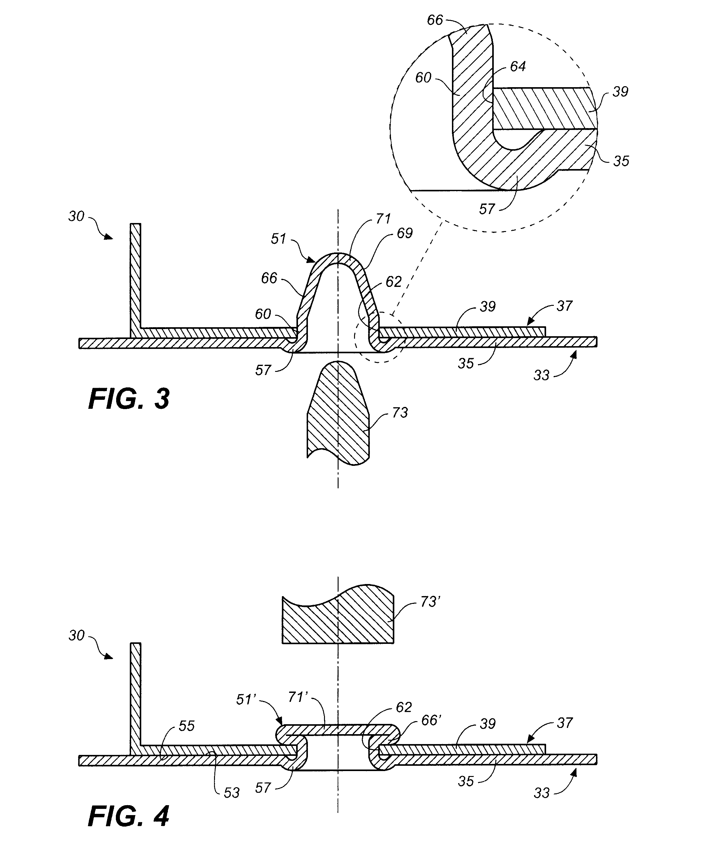
[0009] One aspect of the present invention is directed to a plane-to-plane joint for securing planar segments of one or more sheet materials together. The plane-to-plane joint includes a first planar segment having an upper planar surface, a second planar segment having a lower planar surface, a joinder structure monolithically formed on the first planar segment, which joinder structure includes a transition zone located below the upper planar surface and a registration zone extending upwardly from the

Problems solved by technology

While such mechanical fasteners are quite effective in securing the overlapping portions together, they increase the number of parts required to create a structure.
Furthermore, such mechanical fasteners generally increase the time, labor and / or costs involved in creating the structure.
Again, such means are quite effective in securing overlapping sheet materials together, but such means also increase time, labor and / or costs involved.
For example, welding requires the use of skilled labor and / or the use of expensive and complex automated welding equipment.
One major disadvantage of such means is that registration of the overlapping portions, that is, the precise alignment of one overlapping portion with respect to the other, must be accomplished by other additional means.
The Rapp patent, however fails to disclose any means provided on the thin plates adjacent the swaged connection which effect registration of the thin plates to one another prior to swaging the plates together.

Method used


Image

  • Method for joining planar sheets and sheets therefor
  • Method for joining planar sheets and sheets therefor
  • Method for joining planar sheets and sheets therefor

Examples


Embodiment Construction

[0028] Reference will now be made in detail to the preferred embodiments of the invention, examples of which are illustrated in the accompanying drawings. While the invention will be described in conjunction with the preferred embodiments, it will be understood that they are not intended to limit the invention to those embodiments. On the contrary, the invention is intended to cover alternatives, modifications and equivalents, which may be included within the spirit and scope of the invention as defined by the appended claims.

[0029] Assignee's following U.S. Patent Application and Patents set forth in considerable detail apparatus and methods for bending or folding sheet materials to form three dimensional structures: 60 / 720,417 entitled METHOD FOR FORMING ANGLES AND CLOSURES IN SHEET MATERIAL AND SHEET THEREFOR; 11 / 180,398 entitled METHOD FOR INCREASING THE FATIGUE RESISTANCE OF STRUCTURES FORMED BY BENDING SLIT SHEET MATERIAL AND PRODUCTS RESULTING THEREFROM; 60 / 682,057 entitled ...


PUM


Abstract

A plane-to-plane joint is configured for securing planar segments of one or more sheet materials together without the need for additional fasteners. The plane-to-plane joint includes a first planar segment having an upper planar surface, a second planar segment having a lower planar surface, a joinder structure monolithically formed on the first planar segment, the joinder structure including a transition zone located below the upper planar surface and a registration zone extending upwardly from the transition zone and out-of-plane from the planar segment, and an aperture in the second planar segment for receiving the joinder structure. The aperture is dimensioned and configured to cooperate with the registration zone of the joinder structure to register the relative position of the first and second planar segments when the lower planar surface abuts against the upper surface. A method of making and using the plane-to-plane joint is also disclosed.

Description

BACKGROUND OF THE INVENTION [0001] 1. Field of the Invention [0002] The present invention relates, in general, to apparatus and methods for joining together planar segments of sheet material(s), and more particularly, relates to a plane-to-plane joint having joinder structures capable of accurately registering planar segments to one another for precise, fastener-free coupling. [0003] 2. Description of Related Art [0004] Various methods may be employed to form three-dimensional structures from two dimensional sheet materials. For example, U.S. Pat. No. 6,877,349 entitled METHOD FOR PRECISION BENDING OF SHEET OF MATERIALS, SLIT SHEETS FABRICATION PROCESS, and U.S. Pat. No. 6,481,259 entitled METHOD FOR PRECISION BENDING OF A SHEET OF MATERIAL AND SLIT SHEET THEREFOR, both to Industrial Origami, LLC, the assignee of the present invention, set forth in considerable detail apparatus and methods for precisely controlling bending or folding of sheet materials along fold lines to form three...

Claims


Application Information

Patent Timeline
IPC IPC(8): B23P11/00F16G11/05
CPCB21D39/031B21D39/032Y10T29/49826F16B17/008Y10T403/4908F16B5/045B21D28/00
Inventor DURNEY, MAX W.
Owner IND ORIGAMI INC CA US
Learn More