
Message buffer for a receiver apparatus on a communications bus

a receiver and communication bus technology, applied in the direction of instruments, data switching networks, liquid/fluent solid measurement, etc., can solve the problems of increasing the wake-up time of such powerful processors, reducing the power consumption of the nodes of such networks, and affecting the operation of the controller nod

Inactive Publication Date: 2007-10-04
NORTH STAR INNOVATIONS
View PDF7 Cites 71 Cited by
  • Summary
  • Abstract
  • Description
  • Claims
  • Application Information

AI Technical Summary

Benefits of technology

"The invention is about a solution for reducing power consumption in a receiver apparatus for a communications bus, especially in controller nodes. The problem is that current solutions require the controller to be powered at all times or to have an auxiliary controller to quickly respond to the first message on the bus. This invention proposes a more efficient solution that allows the main controller to draw a low quiescent current in a sleep state and quickly respond to the first message without losing information in the first message."

Problems solved by technology

Reducing power consumption of the nodes of such networks, especially of the controller node, is often critical, especially during waiting periods when the controlled nodes are inactive.
However, waking the functions up and restoring supplies to the switched off modules to retrieve the normal run condition of the module or node introduces a greater or lesser delay that may be more or less acceptable for a given function.
Unfortunately, this trend increases the wake-up time of such powerful processors because the clocks need to restart and stabilize.
As will be appreciated, use of sleep and stop modes to decrease power consumption has created a problems in typical multiplexed bus systems with minimum controller wake-up requirements, and particularly in CAN networks where these minimum wake-up and response time are becoming increasingly shortened.
As a result of the deep sleep or stop modes of CAN nodes, the corresponding information in the first CAN message received off the bus is typically lost because that node's MCU cannot wake up sufficiently fast to decipher the first message.
These solutions present significant reductions in performance and response time of the node.
However, adding an additional MCU increases costs significantly.

Method used


Image

  • Message buffer for a receiver apparatus on a communications bus
  • Message buffer for a receiver apparatus on a communications bus
  • Message buffer for a receiver apparatus on a communications bus

Examples


Embodiment Construction

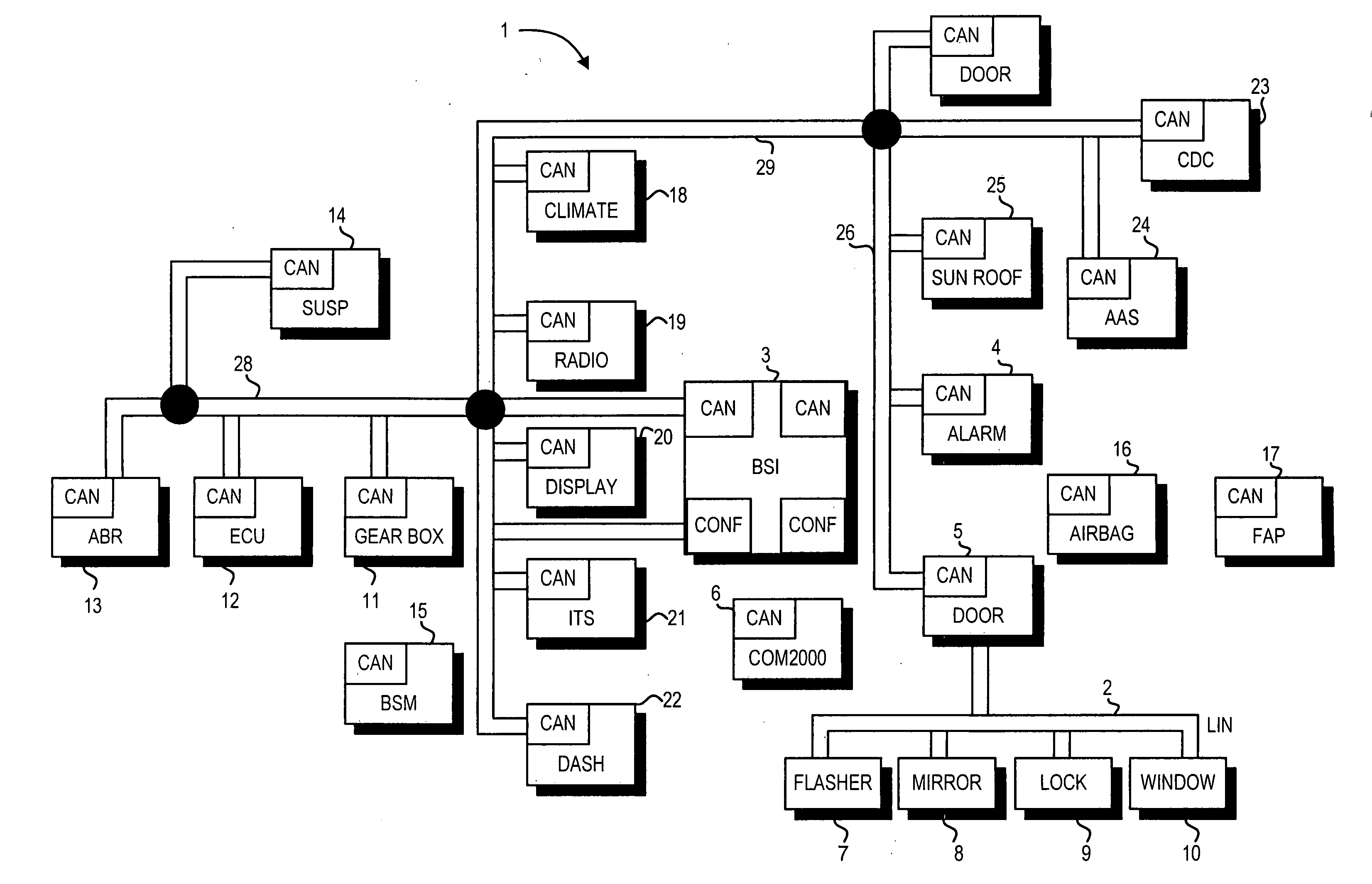
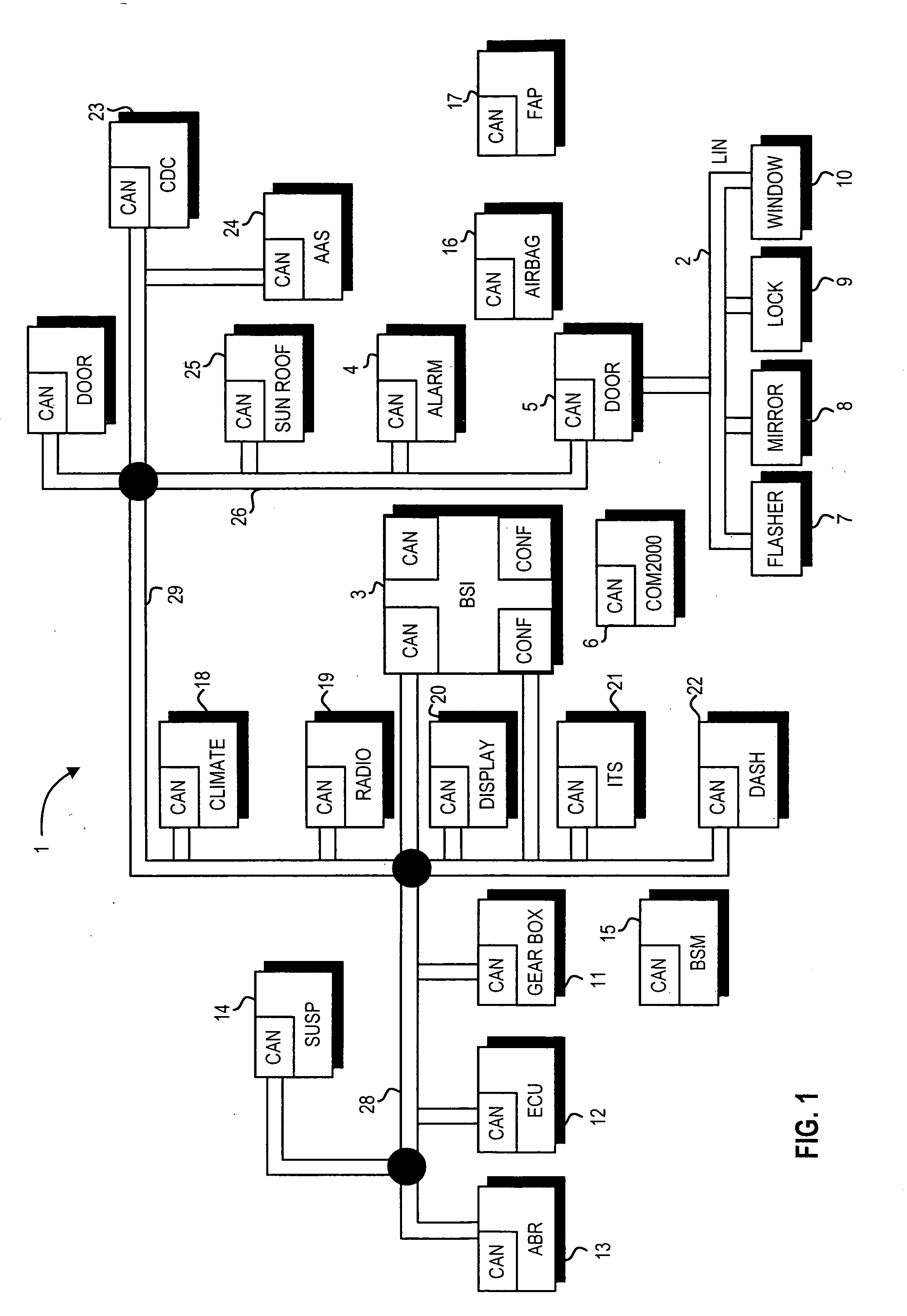
[0018] In the following detailed description of preferred embodiments of the invention, specific exemplary embodiments in which the invention may be practiced are described in sufficient detail to enable those skilled in the art to practice the invention, and it is to be understood that other embodiments may be utilized and that logical, architectural, programmatic, mechanical, electrical and other changes may be made without departing from the spirit or scope of the present invention. The following detailed description is, therefore, not to be taken in a limiting sense, and the scope of the present invention is defined only by the appended claims. In particular, although the preferred embodiment is described below with respect to a CAN communication device in an automotive vehicle, it will be appreciated that the present invention is not so limited and that it has application to other embodiments of multiplexed communication networks.

[0019] With reference now to the figures, and i...


PUM


Abstract

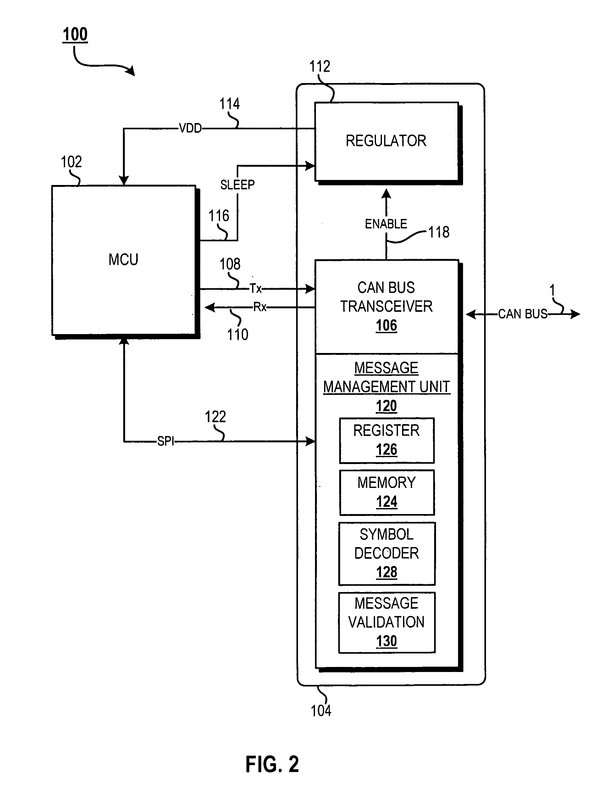
A Controller Area Network (CAN) node consists of a high-powered microcontroller, a low standby power regulator, a CAN bus transceiver, and a minimal CAN message buffer for storing received messages. Low power standby operation allows for the controller to power off, while the transceiver and regulator are operated in standby. The transceiver / regulator will enter run mode after the first symbol of a received CAN message is validated off the bus. As the original CAN message is received, it is buffered in the message buffer and, after stored, a status register is set to indicate the full message has been received. Once the controller has stabilized out of a wake-up mode, it retrieves the stored message and acts accordingly. The CAN message buffer is coupled to the controller by an system packet interface (SPI) interface for transmission of a controller wake-up command and retrieval of a buffered message.

Description

BACKGROUND OF THE INVENTION [0001] 1. Field of the Invention [0002] This invention relates to a receiver apparatus for a communications bus, and in particular to a management unit for a receiver apparatus on a communications bus. [0003] 2. Description of the Related Art [0004] Local networks often make use of a communications bus over which a set of nodes communicates. A driver module in a controller node transmits step-change signals over the bus to receivers in remote controlled nodes. The step-change signal activates the multiplexed remote nodes connected to the bus, and the bus also selectively transmits signals from the remote nodes back to a receiver in the controller node. [0005] Historically, in automotive applications, functions such as door locks, seat positions, electric mirrors, and window operations have been controlled directly by electrical direct current delivered by wires and switches. Such functions may today be controlled by ECUs (Electronic Control Units) togethe...

Claims


Application Information

Patent Timeline
Patent Type & Authority Applications(United States)
IPC IPC(8): H04L12/56
CPCH04L12/40039H04L2012/40273H04L2012/40215H04L12/66
Inventor HU, CARL C.GAUEN, KIM R.
Owner NORTH STAR INNOVATIONS
Learn More