
Lock bolt release system and method

a technology of locking bolts and release systems, applied in the direction of fastening means, mechanical devices, carpet fasteners, etc., can solve the problems of increasing the cost of the lock, and the inability to retract the lock bolt, so as to reduce the size of the security lock and the associated spindle, the effect of reducing the size of the lock case and the size of the power supply

Active Publication Date: 2007-09-27
LOCKMASTERS
View PDF9 Cites 10 Cited by
  • Summary
  • Abstract
  • Description
  • Claims
  • Application Information

AI Technical Summary

Benefits of technology

[0006] The present invention provides a lock bolt release system that is simpler and more reliable than known systems. With the lock bolt release system of the present invention, the security lock and associated spindle are not used to apply forces required to move the lock bolt. Thus, there is substantially greater flexibility in choosing what kind of security lock to use. Further, security locks and associated spindles may be reduced in size; and clearance holes for spindles can be placed in more secure locations or, in some applications, eliminated, thereby improving system security. In addition, the security lock may be located remotely from the door. With smaller security locks, power supplies, if used, experience less of a load and are more reliable.
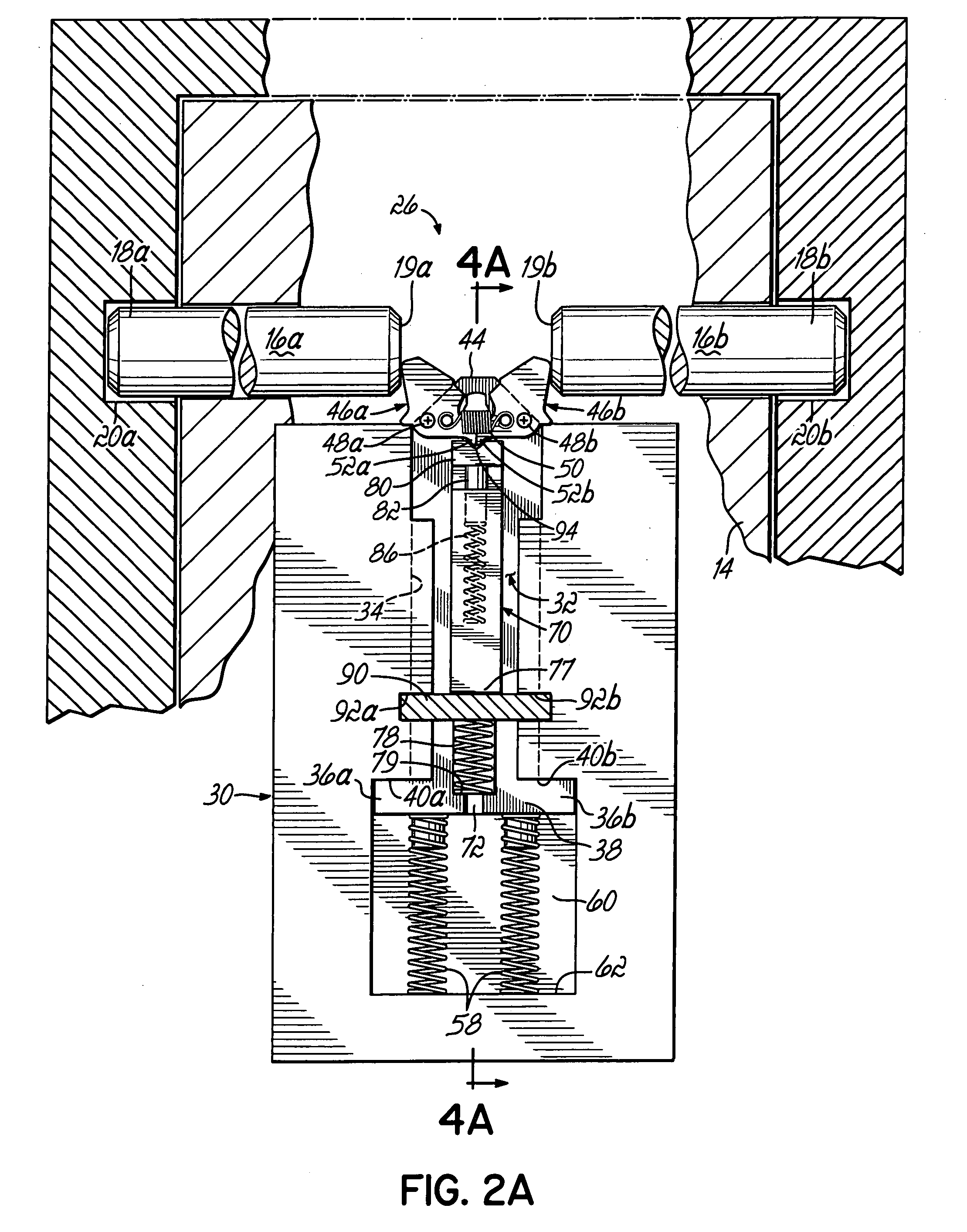
[0007] According to the principles of the present invention and in accordance with the described embodiments, the invention provides an apparatus for use with a door providing access to a secure area. A door bolt is movable with respect to the door, and the door bolt is engageable and disengageable with structure to respectively lock and unlock the door. The door supports a lock bolt that has a pawl pivotally mounted on a distal end. The pawl is pivotable by the door bolt. A wedge block is movably mounted on the lock bolt and is movable by the pawl from a first position blocking a pivoting of the pawl to a second position allowing the pawl to pivot. A stop member is located adjacent the wedge block and is movable between a first location and a second location. In the first location, the stop member blocks motion of the wedge block from the first position and thus, prevents the door bolt from being disengaged from the structure and maintains the door locked. At the second location, the stop member unblocks motion of the wedge block and thus, permits the door bolt to be disengaged from the structure and allows the door to be opened.

Problems solved by technology

Non-ideal conditions or multiple closely-spaced entries may deplete the power supply such that the lock bolt cannot be retracted upon entry of a proper combination.
Increasing the capacity of the power supply may minimize such occurrences; however, a larger power supply increases the size of the lock case as well as the cost of the lock.

Method used


Image

  • Lock bolt release system and method
  • Lock bolt release system and method
  • Lock bolt release system and method

Examples


Embodiment Construction

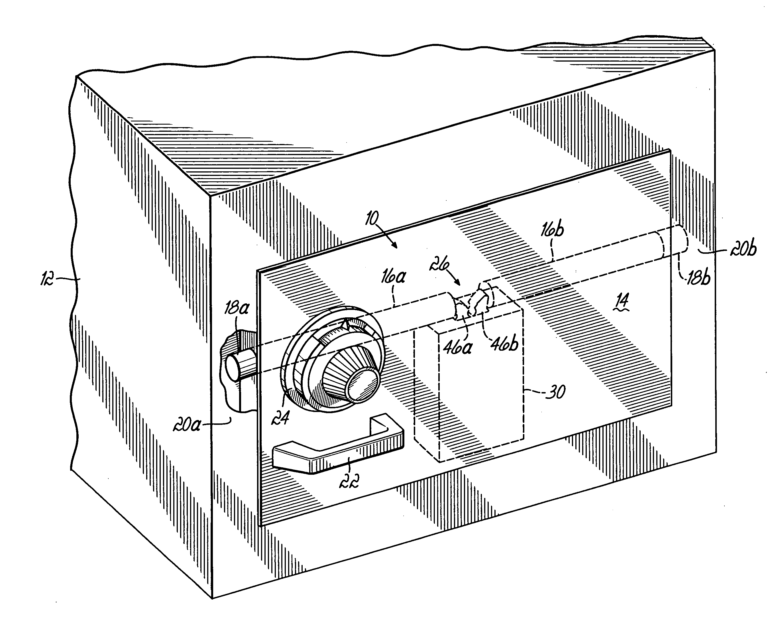
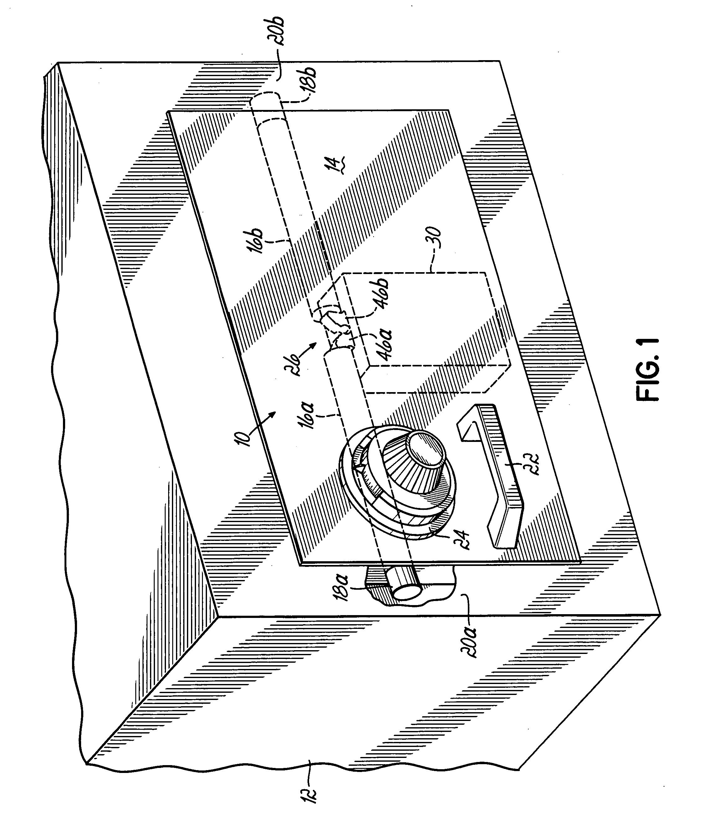
[0017] Referring to FIG. 1, in one exemplary application of a lock bolt system 10, a case 12, which represents a securable volume, is closed by a door 14 that may or may not be hinged to the case 12. The case 12 and door 14 are representative of a securable volume, for example, a lock box, a safe, a room, etc. Further, the case 12 and door 14 may be of any material, size and shape commensurate with the nature of the items to be secured and the level of security required by the application.

[0018] Door bolts 16a, 16b are mounted in the door 14 for respective longitudinal sliding motions or translations. Door bolt ends 18a, 18b slide into, or behind, respective structures 20a, 20b of the case 12, thereby prohibiting the door 14 from opening with respect to, or being removed from, the case 12. The door bolts 16a, 16b are operatively connected to a pivotable handle 22. Rotating the handle 22 in one direction, for example, a counterclockwise direction, is effective to translate the door ...


PUM


Abstract

A lock bolt release system operable with a door bolt supported by a door providing access to a secure area. A pawl is pivotally mounted on a distal end of a lock bolt, and the pawl is pivoted by operation of the door bolt prior to the lock bolt being movable by the door bolt. A wedge block is movably mounted on the lock bolt and is effective to block motion of the pawl and the door bolt. A stop member is located adjacent the wedge block and blocks motion of the wedge block, thereby preventing the door bolt from being disengaged from the structure. The stop member is movable, which permits the wedge block to be moved by the pawl and the door bolt to contact and move the lock bolt, thus, permitting the door bolt to be disengaged from the structure.

Description

FIELD OF THE INVENTION [0001] The present invention is directed generally to a lock bolt system and, more particularly, to a lock bolt system used on doors that are opened to provide access to secure areas. BACKGROUND OF THE INVENTION [0002] The use of lock bolts for security purposes is widespread to control access to items stored in lockable, high-security enclosures, such as vaults, safes, and cabinets. A door to the enclosure is often secured against opening by one or more extended door bolts. An internal lock bolt prohibits the door bolts from being retracted using an external handle. When using a combination type lock, entry of a proper combination permits the exterior handle to be used to release the lock bolt and retract door bolts, thereby unlocking the door and permitting it to be opened. [0003] Often, the combination lock or other security lock is coupled by a spindle to a mechanism that retracts the lock bolt; and therefore, the spindle must be large enough to apply the ...

Claims


Application Information

Patent Timeline
Patent Type & Authority Applications(United States)
IPC IPC(8): E05C1/06
CPCE05B47/0607E05B47/0002E05B17/2084E05B65/0075Y10S292/51Y10T292/0836Y10T292/096Y10T292/1028
Inventor JASPER, THOMAS E.
Owner LOCKMASTERS
Learn More