
Storage system comprising microprocessor load distribution function

a technology of load distribution and microprocessor, applied in the field of storage systems, can solve the problems of excessive load on this microprocessor, delay in processing i/o requests,

Inactive Publication Date: 2007-09-20
HITACHI LTD
View PDF9 Cites 26 Cited by
  • Summary
  • Abstract
  • Description
  • Claims
  • Application Information

AI Technical Summary

Benefits of technology

[0007] Hence an object of this invention is to prevent the concentration of loads at a single microprocessor in a storage system comprising a plurality of microprocessors.

Problems solved by technology

At this time, if a plurality of I / O requests are concentrated at a single microprocessor, the load on this microprocessor becomes excessive, and there is the possibility that processing of I / O requests will be delayed.

Method used


Image

  • Storage system comprising microprocessor load distribution function
  • Storage system comprising microprocessor load distribution function
  • Storage system comprising microprocessor load distribution function

Examples


Embodiment Construction

[0049] Below, aspects of the invention are explained, referring to the drawings.

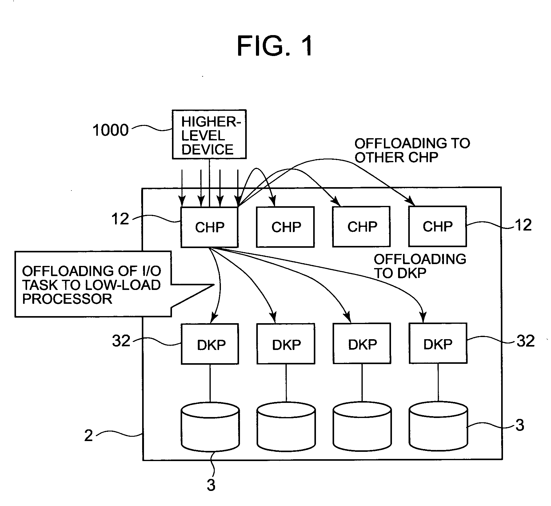
[0050]FIG. 1 shows one concept of the characteristics of an aspect of the invention.

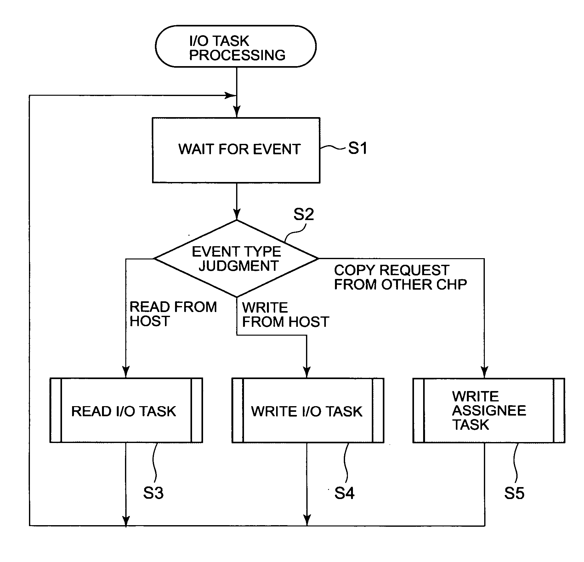
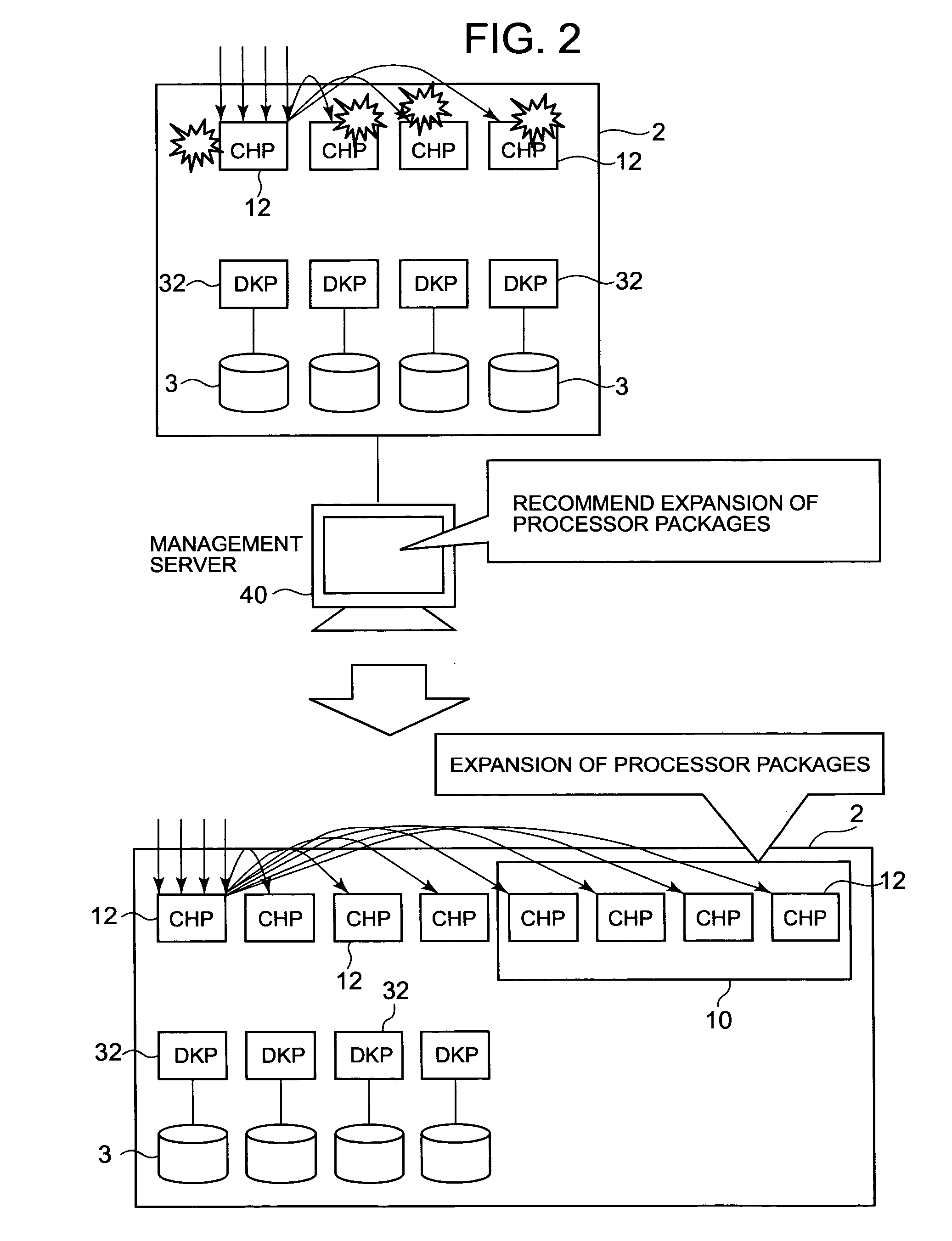
[0051] The storage system 2 comprises a plurality of storage devices 3; one or more microprocessors (hereafter abbreviated to “DKP”) 32, which performs input / output of data to and from one or more storage devices 3; and a plurality of microprocessors (hereafter abbreviated to “CHP”) 12 which perform processing of I / O requests issued from a higher-level device 1000. In this storage system 2, a CHP 12, having received an I / O request (write request or read request) from the higher-level device 1000, assigns at least the portion of the task of processing the I / O request (hereafter called an I / O task) which involves a high load (for example, cache hit judgment, described below, or cache locking), to another CHP 12 or to a DKP 32. By this means, the assigner CHP 12 is freed from execution of at least that part of processing o...


PUM


Abstract

Among a plurality of microprocessors 12, 32, when the load on a microprocessor 12 which performs I / O task processing of received I / O requests is equal to or greater than a first load, the microprocessor assigns at least an I / O task portion of the I / O task processing to another microprocessor 12 or 32, and the other microprocessor 12 or 32 executes at least the I / O task portion. The I / O task portion is a task processing portion comprising cache control processing, comprising the securing in cache memory 20 of a cache area, which is one area in cache memory 20, for storage of data.

Description

CROSS-REFERENCE TO PRIOR APPLICATION [0001] This application relates to and claims priority from Japanese Patent Application No. 2006-73867, filed on Mar. 17, 2006, the entire disclosure of which is incorporated herein by reference. BACKGROUND OF THE INVENTION [0002] 1. Field of the Invention [0003] This invention relates to a storage system comprising a plurality of microprocessors. [0004] 2. Description of the Related Art [0005] As one storage system of this type, for example, the storage system disclosed in Japanese Patent No. 3264465 is known. This storage system has a plurality of higher-level-connected logical devices, forming an interface to a higher-level system; storage devices; a plurality of storage-device-connected logical devices, forming an interface to the storage devices; and a cache memory device (a cache memory device shared by the plurality of higher-level-connected logical devices and by the plurality of storage-device-connected logical devices), which temporaril...

Claims


Application Information

Patent Timeline
IPC IPC(8): G06F9/46
CPCG06F3/061G06F3/0631G06F3/0658G06F2209/509G06F3/0689G06F9/5027G06F12/0866G06F3/0659
Inventor SUGIMOTO, SADAHIROSHIMOZONO, NORIOSERIZAWA, KAZUYOSHI
Owner HITACHI LTD
Learn More