Methods and apparatus to use engine valves as both intake and exhaust valves

a technology of engine valves and intake and exhaust, which is applied in the direction of valve arrangements, machines/engines, non-mechanical valves, etc., can solve the problem of limiting the amount of this

Inactive Publication Date: 2007-09-20
STURMAN DIGITAL SYST
View PDF15 Cites 6 Cited by
  • Summary
  • Abstract
  • Description
  • Claims
  • Application Information

AI Technical Summary

Problems solved by technology

However, there is a limit as to how much this can achieve, as all four valves must ge

Method used


Image

  • Methods and apparatus to use engine valves as both intake and exhaust valves
  • Methods and apparatus to use engine valves as both intake and exhaust valves
  • Methods and apparatus to use engine valves as both intake and exhaust valves

Examples


Embodiment Construction

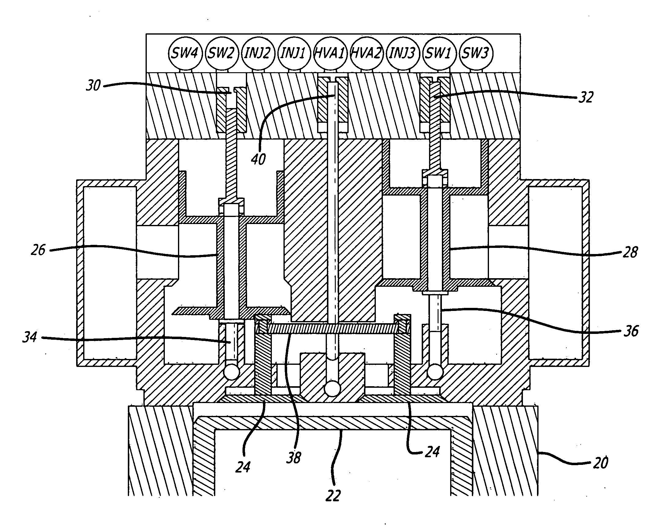
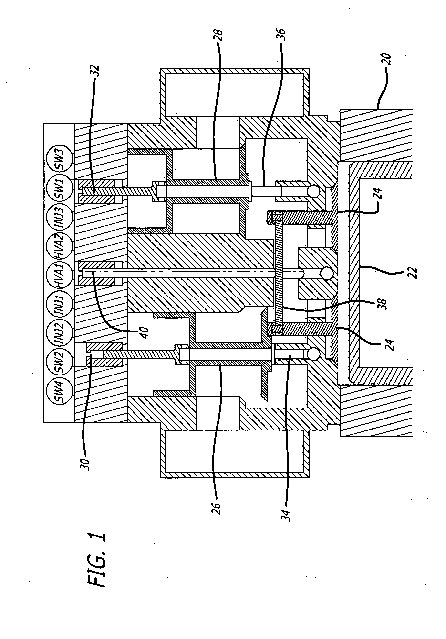
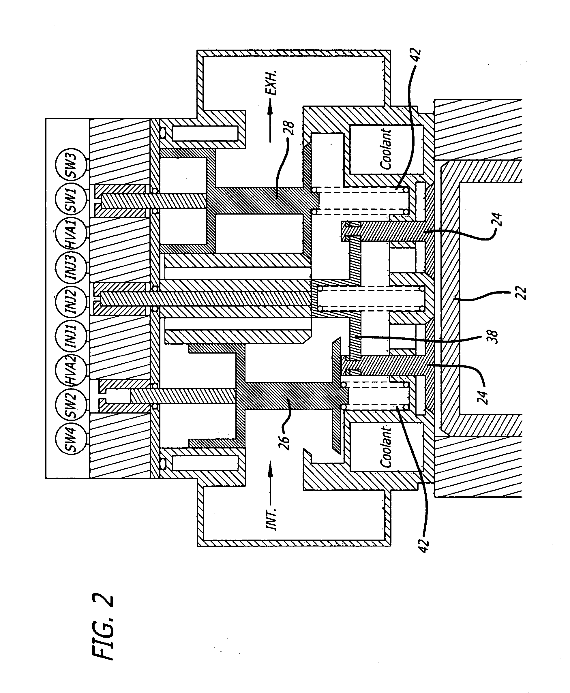
[0014] The preferred embodiments of the present invention are intended to be used on diesel engines, though this is not a limitation of the invention, as the invention is also applicable to gasoline engines, or engines intended to operate on other fuels. Also, while the present invention is preferably to be used on turbocharged engines, this too is not a limitation of the invention, as the present invention is also applicable to non-turbocharged engines. Further, the preferred embodiments are intended to be used on engines having multiple intake and multiple exhaust valves, as is characteristic of most modern engines, though this too is a preference, not a limitation of the invention.

[0015] The present invention is intended to increase the volumetric efficiency of engines, in the exemplary embodiments disclosed herein, engines having two intake valves and two exhaust valves per cylinder, by selectively using all four valves, the two intake and the two exhaust valves, as both the in...


PUM


Abstract

Methods and apparatus to selectively use engine valves as both intake and exhaust valves and to selectively operate the engine as a 2 cycle or as a 4 cycle engine. In a disclosed embodiment, the intake valves and the exhaust valves, are manifolded together through a small manifold, with the manifold being connectable to the intake manifold or the exhaust manifold through two-way valves. In preferably a camless engine, the engine valves may be controlled to operate the intake valves as intake valves only or to operate as both intake valves and exhaust valves, and to operate the exhaust valves as exhaust valves only or to operate the exhaust valves as both intake valves and exhaust valves. Exemplary embodiments are disclosed.

Description

CROSS-REFERENCE TO RELATED APPLICATION [0001] This application claims the benefit of U.S. Provisional Patent Application No. 60 / 775,387 filed Feb. 21, 2006.BACKGROUND OF THE INVENTION [0002] 1. Field of the Invention [0003] The present invention relates to the field of the operation and control of engine valves in piston engines. [0004] 2. Prior Art [0005] The present invention is based on the fact that at higher engine speeds and higher power outputs, engines have more difficulty breathing, that is, their volumetric efficiency goes down. Typically modern engines may include, by way of example, two intake valves and two exhaust valves per cylinder to attempt to increase the volumetric efficiency. However, there is a limit as to how much this can achieve, as all four valves must generally fall within a circle of a diameter approximately equal to the piston diameter. BRIEF DESCRIPTION OF THE DRAWINGS [0006]FIG. 1 is a schematic cross-section through an engine head illustrating one emb...

Claims


Application Information

Patent Timeline
IPC IPC(8): F01L9/02F01L9/04
CPCF01L1/28F01L15/04F01L5/04F01L1/44
Inventor STURMAN, ODED EDDIE
Owner STURMAN DIGITAL SYST
Why Eureka
Try Eureka