Fuel Supply Control Method Applied to Exhaust Gas Control Apparatus for Internal Combustion Engine and Exhaust Gas Control Apparatus to Which the Method is Applied
- Summary
- Abstract
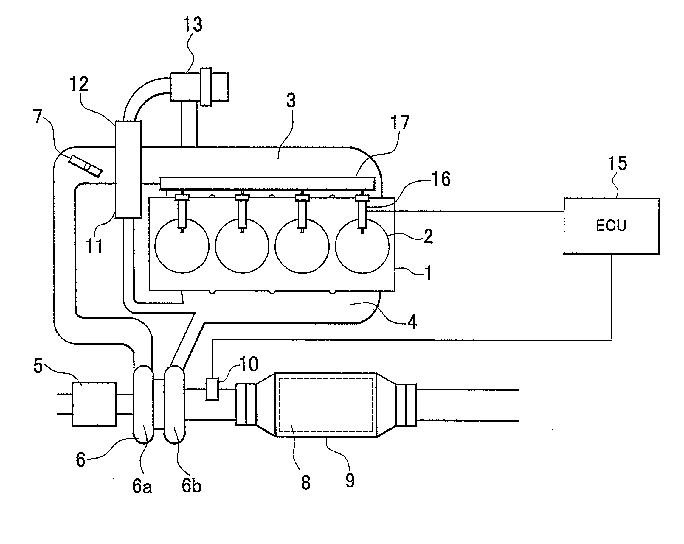
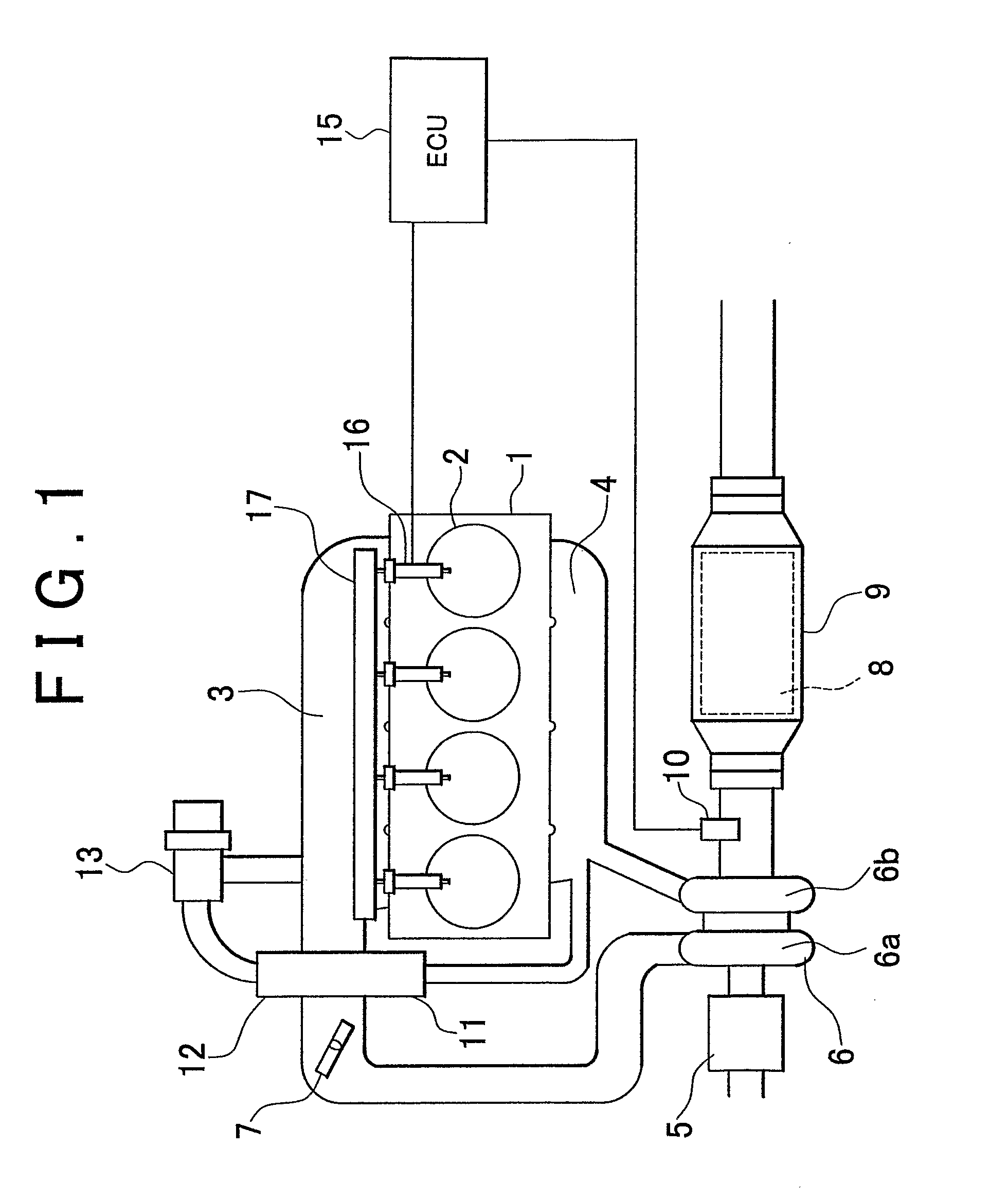
- Description
- Claims
- Application Information
AI Technical Summary
Benefits of technology
Problems solved by technology
Method used
Image

Examples
second embodiment
[0070] In the second embodiment, the ECU 15 performs a fuel supply performing routine in FIG. 5 in parallel with the routine in FIG. 7.
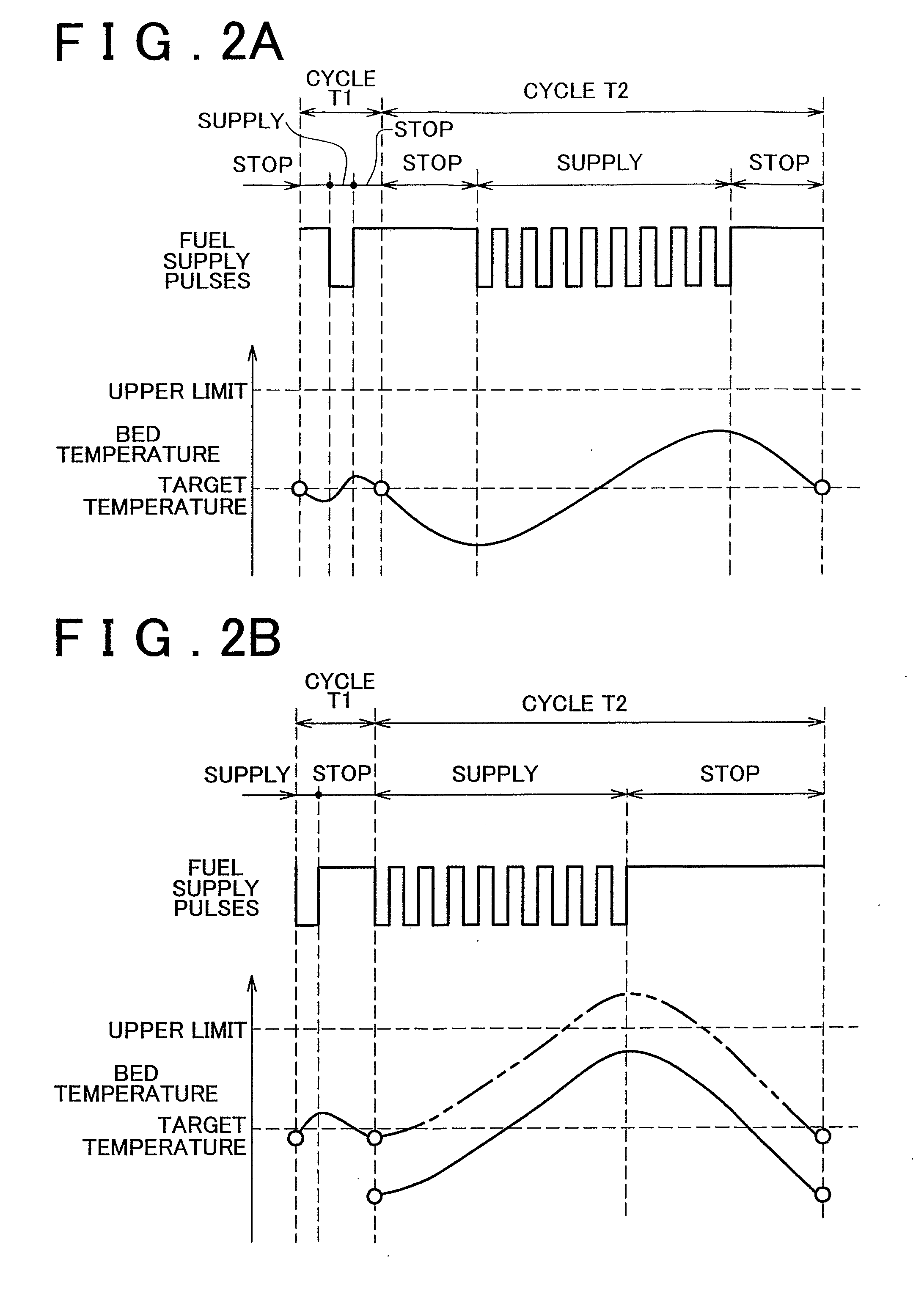
[0071] According to the above-mentioned process, the first lean period fuel supply amount Qlean 1 is corrected based on an amount of change in the first lean period length Tlean 1 that is calculated based on the estimated fuel supply amount Qrichp and the temperature-based required fuel supply amount Qt. For example, when the vehicle is accelerating, the estimated fuel supply amount Qrichp is increased due to an increase in the intake air amount, and also the first lean period length Tlean 1 tends to be increased. In this case, as shown in FIG. 9, the first lean period fuel supply amount Qlean 1 is changed to a higher value. As a result, the time at which an affirmative determination is made in step S9 is delayed, and the time point P2 at which the accumulated temperature-based required fuel supply amount Qtsum becomes equal to the first lean period ...
third embodiment
[0078] In the third embodiment, the ECU 15 serves as fuel supply period correcting means by performing steps S30 to S32, step S300 and step S104.
[0079] Next, a fourth embodiment of the invention will be described with reference to FIGS. 13 to 15. FIG. 13 shows a fuel supply timing control routine in the fourth embodiment. In this routine, after the actual fuel supply amount Qrich is obtained in step S12, it is determined in step S40 whether the actual fuel supply amount Qrich is equal to or smaller than the estimated fuel supply amount Qrichp (the value obtained when the first lean period is completed). When an affirmative determination is made, a fuel supply continuation permission flag is turned ON in step S41, and step S13 is then performed. On the other hand, when it is determined in step S40 that the actual fuel supply amount Qrich has exceeded the estimated fuel supply amount Qrichp (the value obtained when the first lean period is completed), step S42 is performed in which th...
fourth embodiment
[0082] In the fourth embodiment, the ECU 15 serves as the fuel supply period correcting means by performing steps S40 to S42, step S400 and step S104.
[0083] Next, a fifth embodiment of the invention will be described with reference to FIGS. 16 and 17. FIG. 16 shows a fuel supply timing control routine in the fifth embodiment. This routine is the same as the routine in FIG. 4 except that step S50 is provided between step S4 and step S5. Namely, when it is determined in step S4 that the first lean period completion flag is OFF, it is then determined in step S50 whether a sulfur component discharge condition satisfaction flag (hereinafter, referred to as a “S discharge condition satisfaction flag”) is ON. The ECU 15 controls the S discharge condition satisfaction flag by using another routine. The S discharge condition satisfaction flag is turned ON, when the S recovery for the catalyst 8 can be performed. For example, when the air-fuel ratio needs to be controlled to be a lean air-fue...
PUM
 Abstract
Description
Claims
Application Information
 - R&D
- Intellectual Property
- Life Sciences
- Materials
- Tech Scout
- Unparalleled Data Quality
- Higher Quality Content
- 60% Fewer Hallucinations
Browse by: Latest US Patents, China's latest patents, Technical Efficacy Thesaurus, Application Domain, Technology Topic, Popular Technical Reports.
© 2025 PatSnap. All rights reserved.Legal|Privacy policy|Modern Slavery Act Transparency Statement|Sitemap|About US| Contact US: help@patsnap.com