
Powered Tool for Tube Cutting and Treating This Invention Relates to a Powered Tool for Tube Cutting and Treating, and Particularlyy to a Powered Tube Toll Which is Portable and Hand Manipulable

a technology of power tools and tubes, which is applied in the direction of tube shearing machines, manufacturing tools, metal working apparatuses, etc., can solve the problems of not providing continuous treatmen

Active Publication Date: 2007-09-20
TESLA TOOLS
View PDF5 Cites 23 Cited by
  • Summary
  • Abstract
  • Description
  • Claims
  • Application Information

AI Technical Summary

Problems solved by technology

Other prior art cutters are different from the present invention in that they do not provide for continuous cutter feeding, nor for automatic settings for various tube or pipe diameters to be cut, nor for efficient constant cutter feed systems without shock loads to the tube.

Method used


Image

  • Powered Tool for Tube Cutting and Treating This Invention Relates to a Powered Tool for Tube Cutting and Treating, and Particularlyy to a Powered Tube Toll Which is Portable and Hand Manipulable
  • Powered Tool for Tube Cutting and Treating This Invention Relates to a Powered Tool for Tube Cutting and Treating, and Particularlyy to a Powered Tube Toll Which is Portable and Hand Manipulable
  • Powered Tool for Tube Cutting and Treating This Invention Relates to a Powered Tool for Tube Cutting and Treating, and Particularlyy to a Powered Tube Toll Which is Portable and Hand Manipulable

Examples


Embodiment Construction

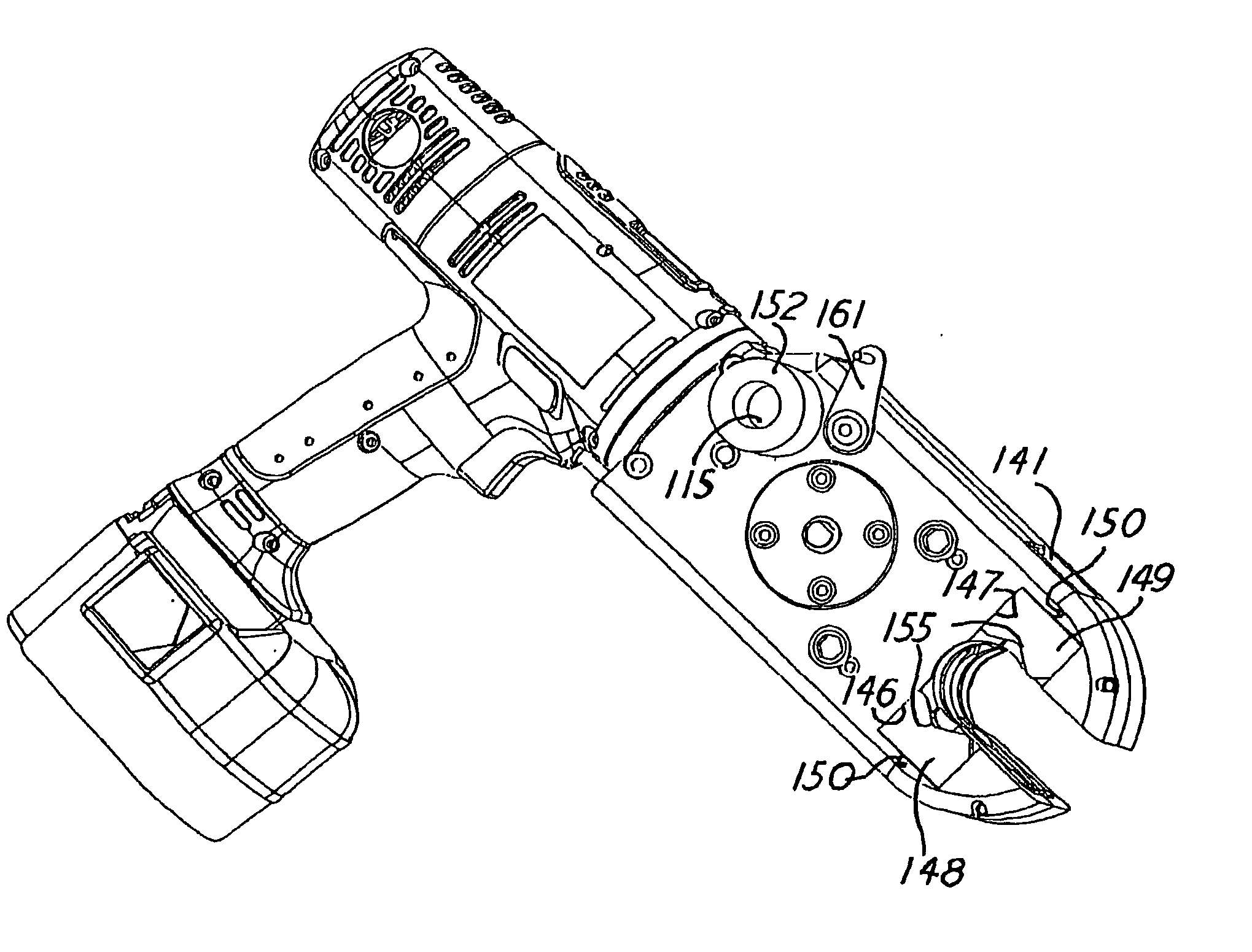
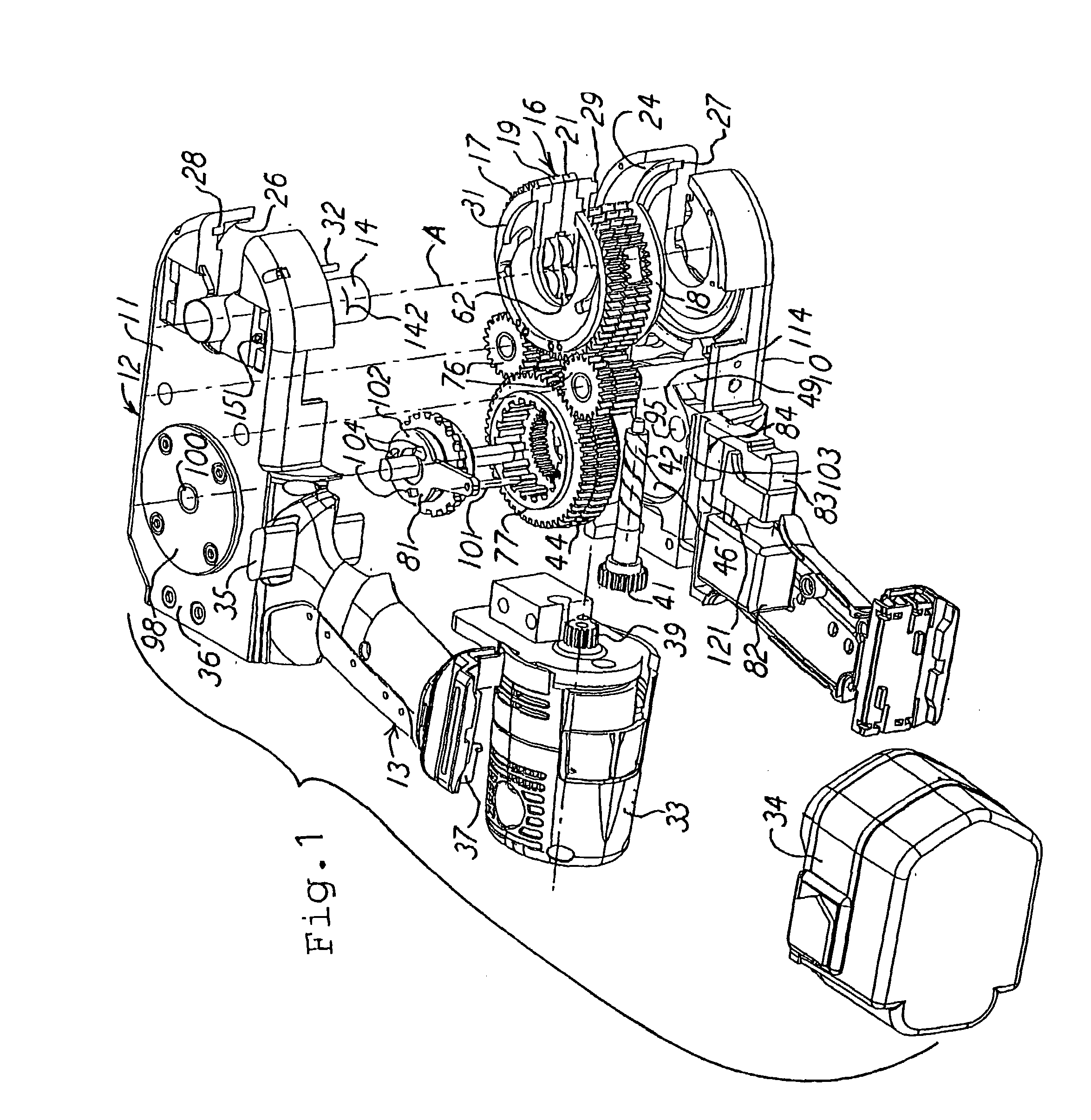
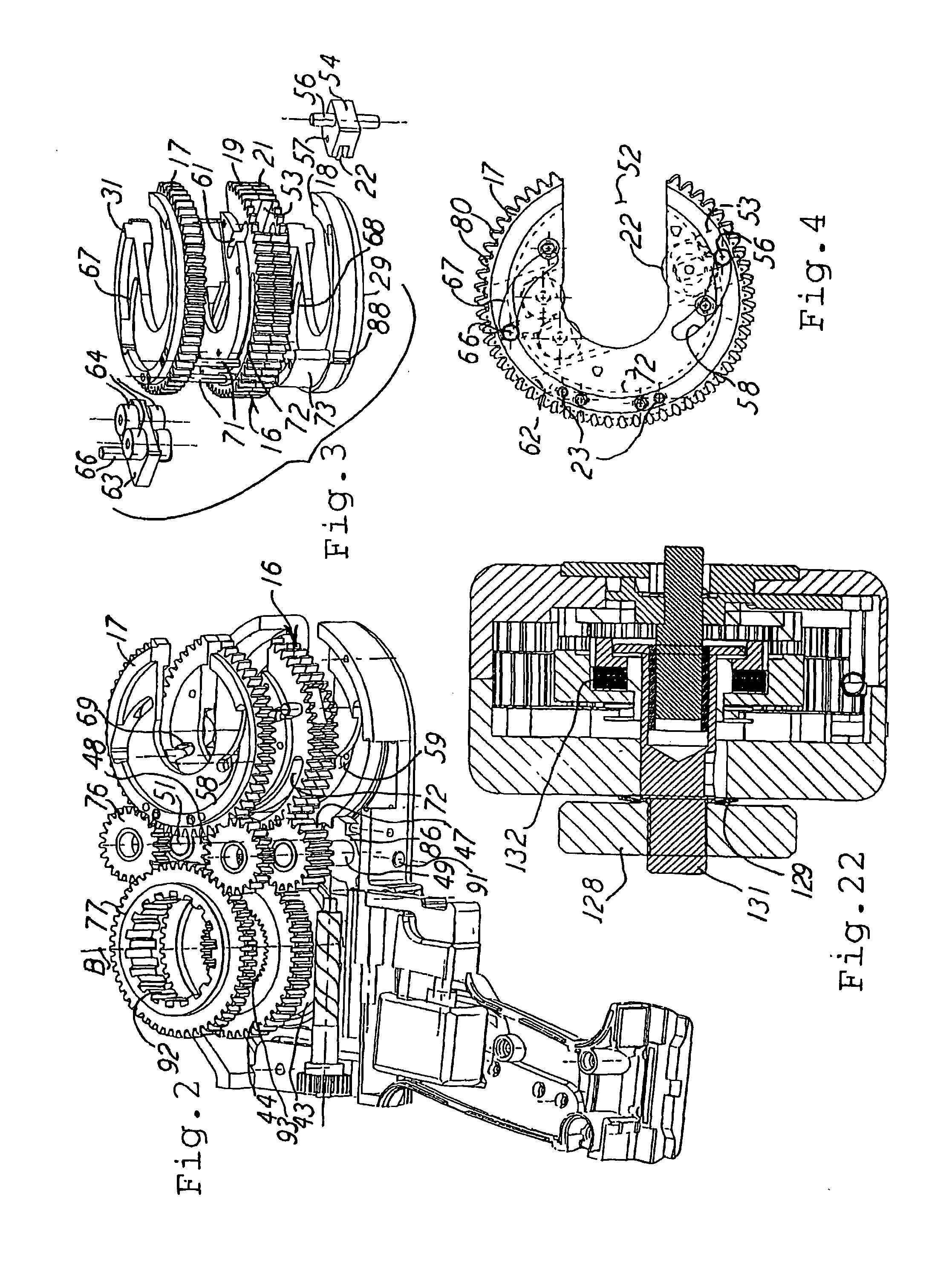
[0027] Generally, there are a tube cutting blade and supporting rollers which engage the tube to be cut and which are automatically positioned to be concentric relative to the longitudinal axis of the tube. Further, the tool is arranged so that a drive reverse to that of the cutting action rotation drive will automatically open the tool for receiving the tube and be automatically centered on the tube during tube cutting. In this description, reference to up, down, top, lower, and that type of orientation simply is in reference to the orientation of the tool as shown in the drawings herein.

[0028] The cutting blade revolves centrally around the tube, and the depth of cut for each revolution is controlled so that tubes of hard material can be cut with one amount of cutting penetration per revolution, and tubes of softer material can be cut with another amount of penetration per revolution. The description herein can be enhanced by reference to my U.S. Pat. No. 6,065,212.

[0029]FIG. 1 ...


PUM

PropertyMeasurementUnit
rotation speedaaaaaaaaaa
diametersaaaaaaaaaa
pitch diameter Daaaaaaaaaa

Abstract

A tool for power cutting and treating a tube or the like, and having a power source and an open end for receiving the tube for cutting. There are a tube cutter and rollers for rotation around the tube during cutting. A tool housing encloses the cutter and rollers and also two gear trains which can rotate at different speeds. One of the trains creates tool rotation drive and the other of the trains creates tube cutting. The rotation drive can be reversed for setting the cutter and rollers in starting positions, along with setting and presenting the open end to the next tube to be cut. The rotating gears also drive two power-take-offs for treating the tube.

Description

[0001] This invention relates to a powered tool for tube cutting and treating, and particularly to a powered tube tool which is portable and hand manipulable. BACKGROUND OF THE INVENTION [0002] Hand held powered tube cutters and treating tools are already known in the prior art, and they are useful in, cutting tubes or pipes on the work site and in restricted spaces. For instance, U.S. Pat. No. 6,065,212 discloses one such tube cutter. Other prior art cutters are different from the present invention in that they do not provide for continuous cutter feeding, nor for automatic settings for various tube or pipe diameters to be cut, nor for efficient constant cutter feed systems without shock loads to the tube. [0003] The present invention provides for a tool of a powered tube cutter which automatically adjusts for different diametrical sizes of tubes. There are self-centering guides which act to place the cutting mechanism centered with the tube, and there is provision for visibly alig...

Claims


Application Information

Patent Timeline
Patent Type & Authority Applications(United States)
IPC IPC(8): B23D21/08
CPCB23D21/04B26D3/16B23D21/08
Inventor LAZAREVIC, MILISAV
Owner TESLA TOOLS
Learn More