
Redundant fieldbus system

a fieldbus system and redundancy technology, applied in the field of automatic or control networks, can solve the problems of undesirable expense, downtime, and physical layer used in the fieldbus network that does not naturally allow redundancy,

Active Publication Date: 2007-09-13
MOORE IND INT
View PDF3 Cites 14 Cited by
  • Summary
  • Abstract
  • Description
  • Claims
  • Application Information

AI Technical Summary

Benefits of technology

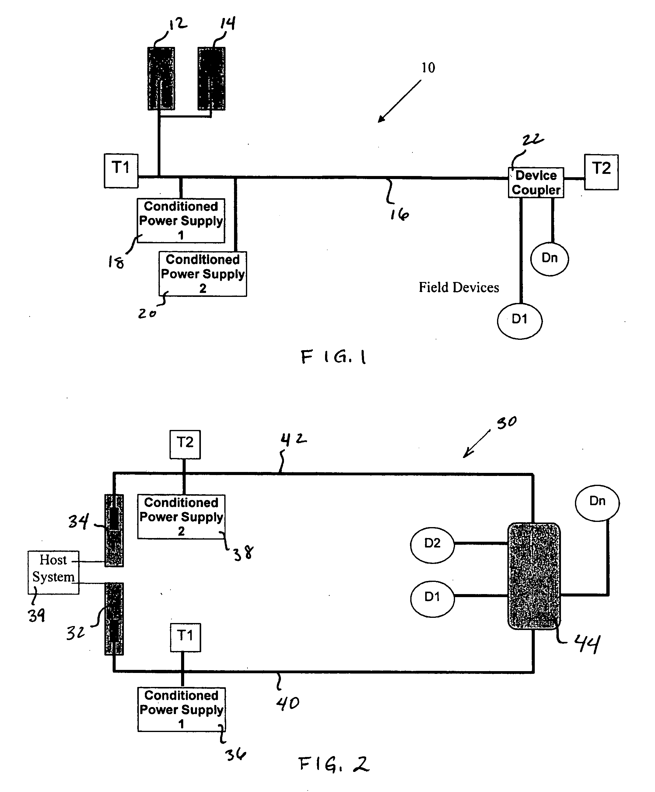
[0010] An aspect of the present invention provides an apparatus for use in a redundant fieldbus system including first terminals adapted to connect to a first fieldbus cable and coupled to a field device to provide power and communications from a fieldbus network to the field device. The apparatus also includes second terminals adapted to connect to a second fieldbus cable and coupled to the field device to provide power and communications from the fieldbus network to the field device. Isolation circuitry is connected between the first terminals and the field device and connected between the second terminals and the field device. The isolation circuitry is adapted to provide power from either the first terminals or the second terminals to the field device and is further adapted to isolate a short circuit between the first terminals from a power source connected to the field device through the second terminals.
[0011] Another aspect of the invention provides

Problems solved by technology

One of the restricting factors in FOUNDATION fieldbus technology is that the physical layer used for the H1 network does not naturally allow for redundancy.
This lack of redundancy may in part lead to undesirable expense and down time for the fieldbus network.

Method used


Image

  • Redundant fieldbus system
  • Redundant fieldbus system
  • Redundant fieldbus system

Examples


Embodiment Construction

[0010] An aspect of the present invention provides an apparatus for use in a redundant fieldbus system including first terminals adapted to connect to a first fieldbus cable and coupled to a field device to provide power and communications from a fieldbus network to the field device. The apparatus also includes second terminals adapted to connect to a second fieldbus cable and coupled to the field device to provide power and communications from the fieldbus network to the field device. Isolation circuitry is connected between the first terminals and the field device and connected between the second terminals and the field device. The isolation circuitry is adapted to provide power from either the first terminals or the second terminals to the field device and is further adapted to isolate a short circuit between the first terminals from a power source connected to the field device through the second terminals.

[0011] Another aspect of the invention provides an apparatus for use in a...


PUM


Abstract

A redundant fieldbus system provides power and communications in a parallel physical configuration between the host system and attached field devices irrespective of any single point failure in the network. In case of a fault, the redundant fieldbus system automatically eliminates the faulty section of the network, switches power and communications to the healthy portion of the network and terminates the network for signal integrity. A device coupler for the system may include a fault detector coupled to an auto-termination circuit that terminates a fieldbus cable when a fault is detected. The device coupler may include fault detection and isolation coupled to each set of spur terminals used to connect field devices to the device coupler. A field device for the system may include circuitry for deselecting a faulty cable while maintaining connection to a healthy cable.

Description

BACKGROUND [0001] 1. Field of the Invention [0002] The present invention relates to an automation or control network such as a fieldbus network that facilitates an extended level of redundancy such as redundancy within the power distribution facilities of a fieldbus network. [0003] 2. Description of the Related Art [0004] Fieldbus networks are advantageously used in industrial control systems and particularly in industrial control systems that provide distributed control incorporating field devices having local processors. A fieldbus network is a two-wire network capable of delivering DC power to remotely installed field devices and capable of providing bidirectional digital communications between the remote field devices and the host system. The digital communications are typically carried on a 31.25 kHz carrier signal in the standard-defined H1 fieldbus network. Various field devices might be attached to be powered from and communicate over the network, including controllers, actu...

Claims


Application Information

Patent Timeline
IPC IPC(8): G05B15/00
CPCG05B9/03
Inventor EL-SAYED, HASSAN M.
Owner MOORE IND INT
Learn More