
Modified boiler wall tube tool

a technology of boiler wall tube and tool, which is applied in the direction of manufacturing tools, soldering devices,auxillary welding devices, etc., can solve the problems that the tools disclosed in the above-mentioned patents are not particularly adapted for use with boiler tubes, and achieve the effect of great versatility

Inactive Publication Date: 2007-09-13
MCCLURE MARK W
View PDF16 Cites 12 Cited by
  • Summary
  • Abstract
  • Description
  • Claims
  • Application Information

AI Technical Summary

Benefits of technology

"The present invention provides a boiler wall tube tool for clampingly securing adjacent ends of boiler tubes in an aligned and adjacent relationship as the ends are connected by welding. The tool comprises a pair of opposed clamp members, each with a recess and a planar wall, and an aperture. The clamp members can be moved towards each other to securely clamp the tubes. The tool provides access to the periphery of the tubes for ease of use and access to the tubes to be welded. The tool can be adjusted to accommodate boiler tubes of different diameters and centering distances. The invention overcomes the disadvantages of prior art methods and devices."

Problems solved by technology

The tools disclosed in the above-mentioned patents are not especially adapted for use with boiler tubes forming a boiler wall.

Method used


Image

  • Modified boiler wall tube tool
  • Modified boiler wall tube tool
  • Modified boiler wall tube tool

Examples


Embodiment Construction

[0017] The detailed description below is for preferred embodiments and is intended to explain the current invention. It is to be understood that a variety of other arrangements are also possible without departing from the spirit and scope of the invention.

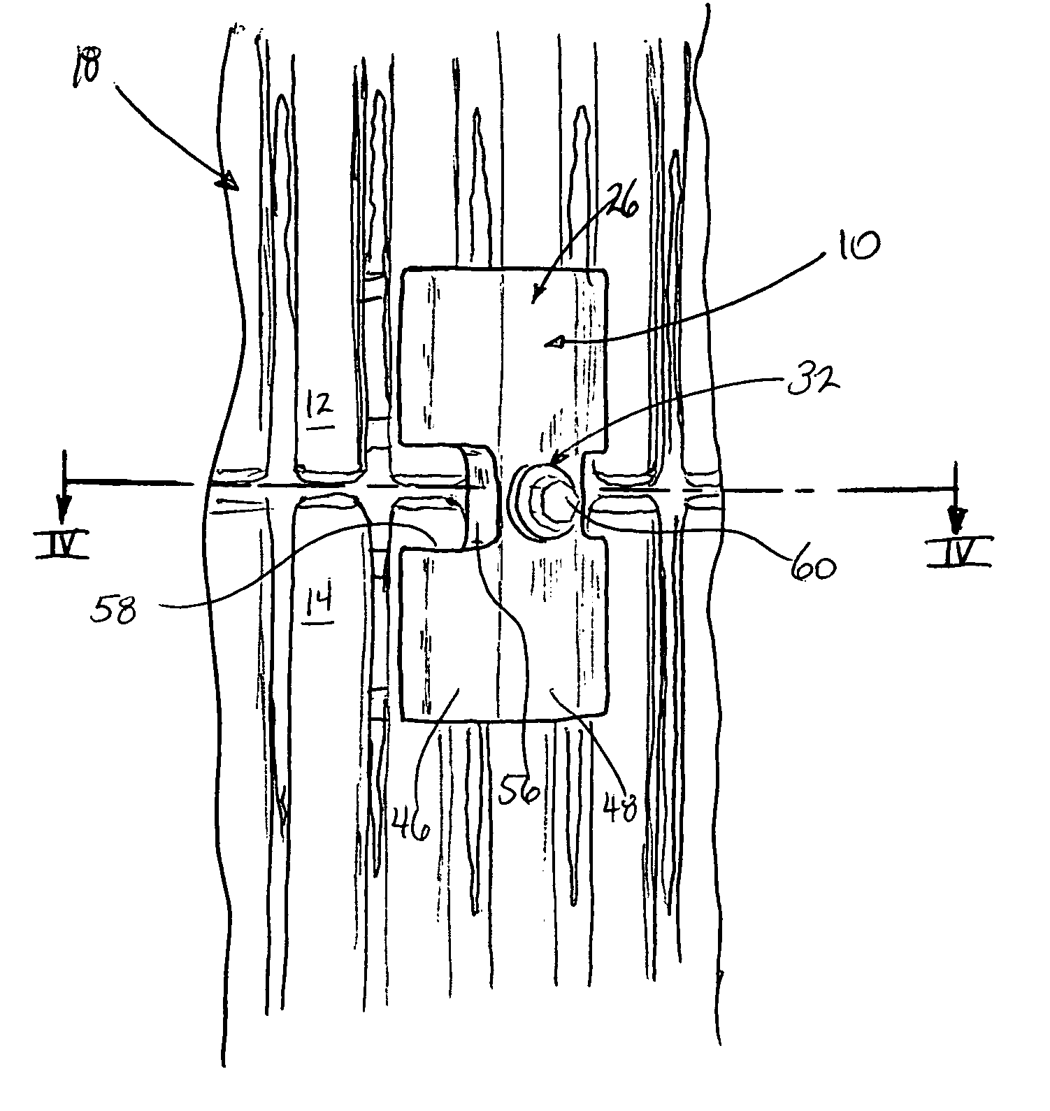
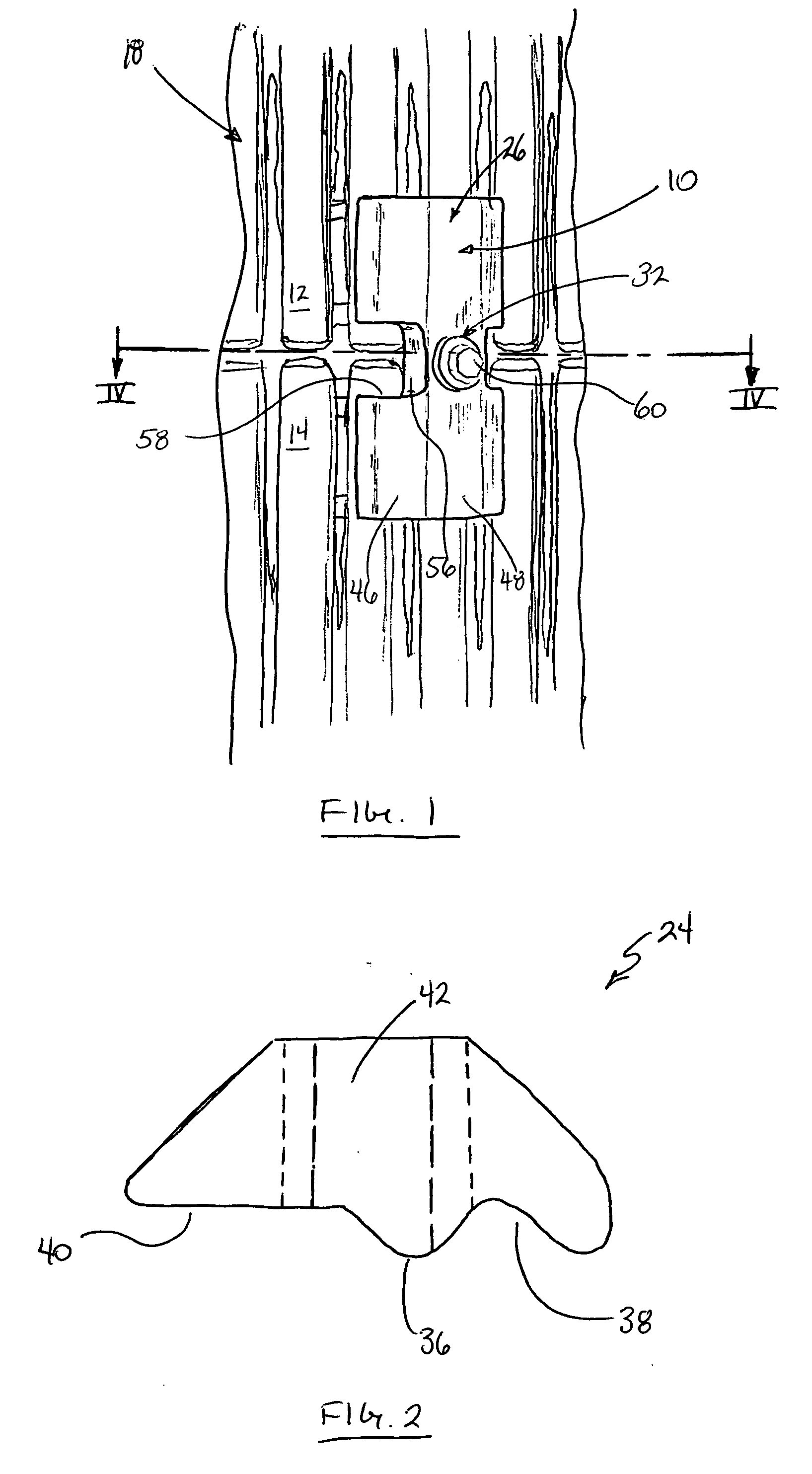
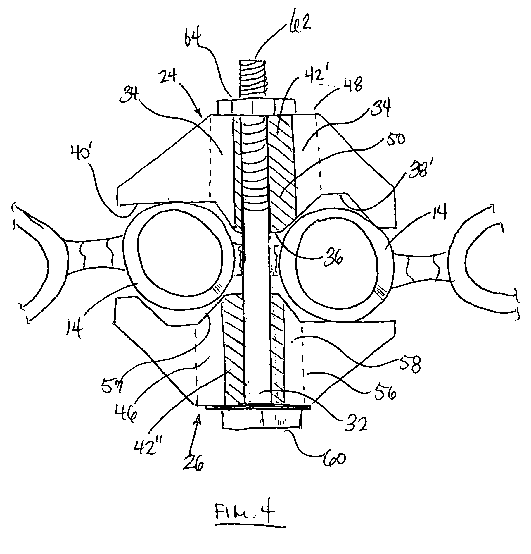
[0018] Referring now specifically to FIGS. 1 through 4 of the drawings, the bolt-type boiler wall tube tool of the present invention is generally designated by reference numeral 10 and is utilized to clampingly secure adjacent tube ends 12 and 14 of two boiler tubes 16 incorporated into a boiler tube wall generally designated by the numeral 18 in which the tubes 16 are spaced a short distance apart and connected by webs 20 which are continuous throughout the length of the tubes 16. In repair or replacement of the tubes 16, it is necessary to remove tube sections and replace them by welding the adjacent ends 12 and 14 together in a manner well understood in this art. In welding the adjacent ends 12 and 14 together, it is essential ...


PUM

PropertyMeasurementUnit
angleaaaaaaaaaa
angleaaaaaaaaaa
sizesaaaaaaaaaa

Abstract

A boiler wall tube tool comprises a pair of opposed clamp members, each one of the clamp members having a nose intermediately disposed between a recess and a planar or inclined wall, and an aperture formed centrally through the clamp member. The clamp members oriented so that the recess of one of the clamp members is substantially aligned with the planar wall of the remaining clamp member for engaging a boiler wall tube therebetween. The aperture of one clamp member is substantially aligned with the aperture of the remaining clamp member. Means for moving the clamp members toward each other for secure clamping engagement of the tubes for maintaining the clamp members in alignment while connecting the ends of the tubes by welding is also provided.

Description

RELATED U.S. APPLICATION DATA [0001] Not applicable. FIELD OF THE INVENTION [0002] This invention relates generally to a tool for use in securing the ends of a boiler tubes along a boiler wall in aligned relation so that the ends of the tubes may be joined via welding. Specifically, this invention relates to a modified boiler wall tube tool in which boiler tubes in the form of a wall can be clampingly secured to retain adjacent ends of the boiler tubes forming the wall in aligned relation when connection the ends of the boiler wall tubes by welding. BACKGROUND OF THE INVENTION [0003] Tools for clamping and aligning boiler tubes when connecting the ends of the boiler tubes by welding are known as disclosed in U.S. Pat. Nos. 4,493,139, 4,579,272 and 4,722,468. The devices disclosed in the above-mentioned patents include structures for securing boiler tube ends in aligned and adjacent relation and function effectively when the boiler tubes are in spaced relation. However, in boiler wal...

Claims


Application Information

Patent Timeline
Patent Type & Authority Applications(United States)
IPC IPC(8): B25B1/20
CPCB23K37/0435Y10T29/53917B25B5/147B23K2201/06B23K2101/06
Inventor MCCLURE, MARK W.
Owner MCCLURE MARK W
Learn More