Holding apparatus for an electronic device
- Summary
- Abstract
- Description
- Claims
- Application Information
AI Technical Summary
Benefits of technology
Problems solved by technology
Method used
Image
Examples
first embodiment
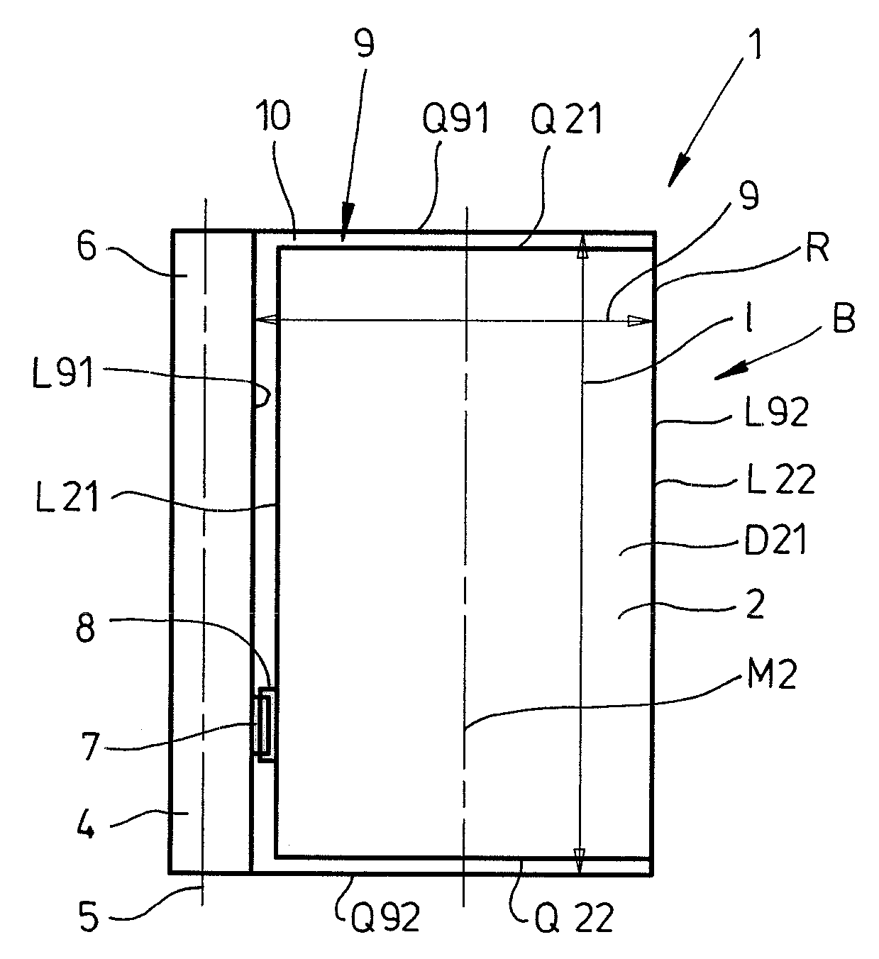
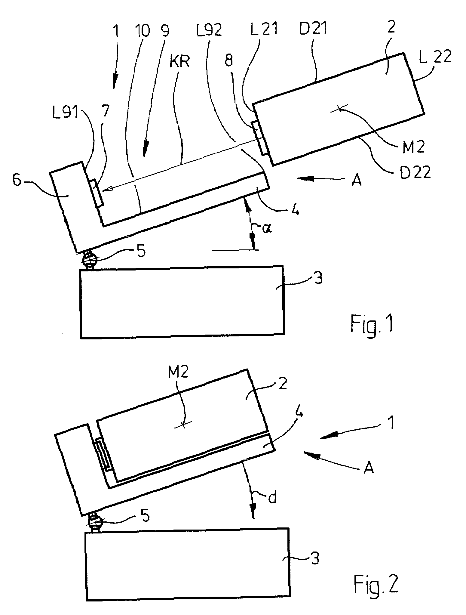
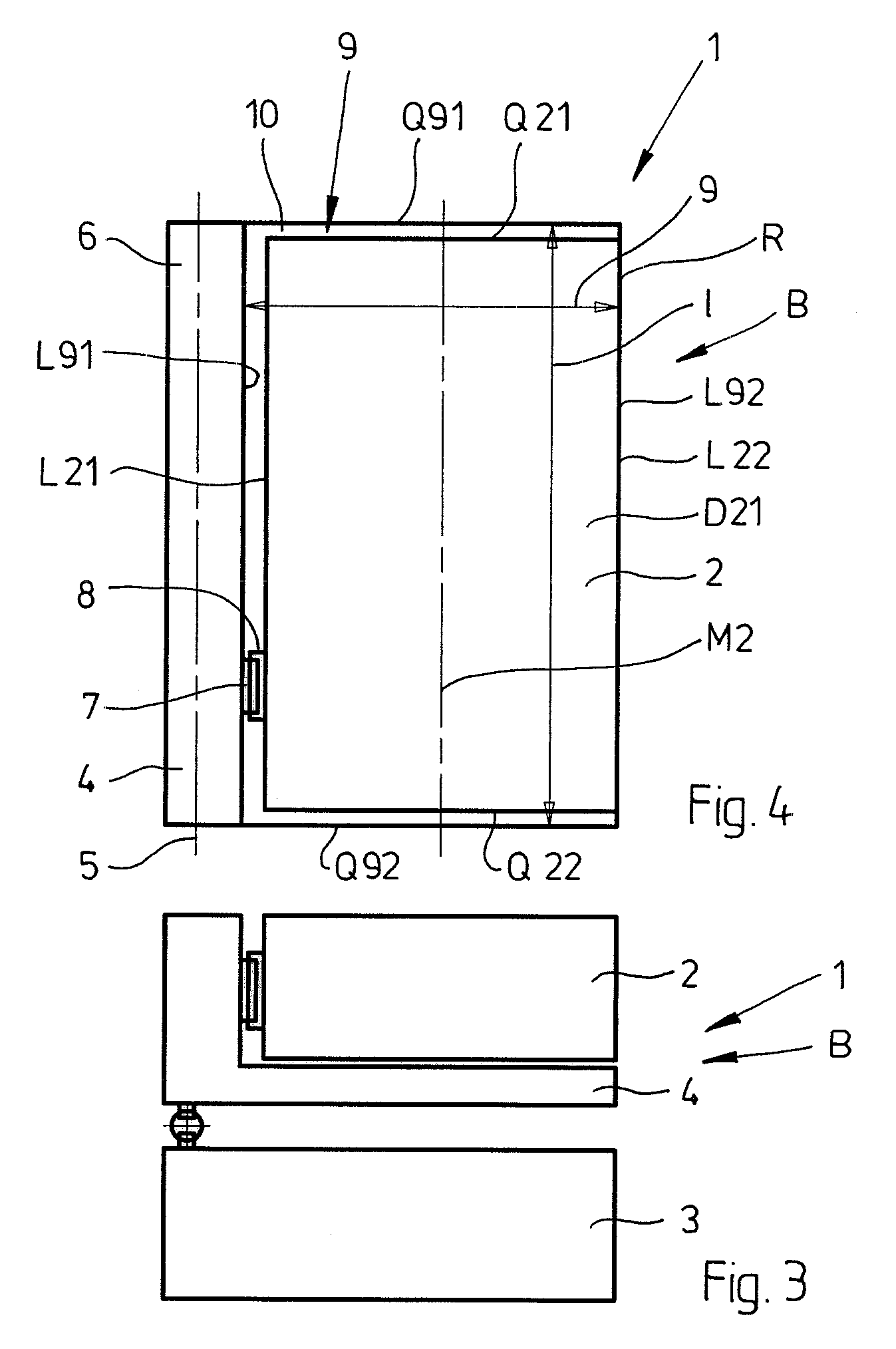
[0031]FIGS. 1 to 3 show a schematically illustrated holding apparatus 1 together with an electronic device 2 in different positions. The holding apparatus 1 comprises a base body 3 and a support 4, it being possible for the support 4 to pivot about a pivot axis 5 in relation to the base body 3. The pivot axis 5 allows support 4 to be positioned in an insertion and removal position A, as shown in FIGS. 1 and 2, respectively, and to also be positioned in holding position B, which is illustrated in FIG. 3. A pivot angle α between the insertion and removal position A and the holding position B is in a range of approximately 15° to 90°, and in particular α=35°. The support 4 has a longitudinal wall 6 which has interface 7 arranged on it to enable the electronic device 2 to make contact. The electronic device 2 is accordingly equipped with an interface 8 which is compatible with interface 7. For contact-making and fixing purposes, electronic device 2 is pushed onto support 4 in a contact-...
fifth embodiment
[0035]FIG. 16 illustrates holding apparatus 1, the design of the holding apparatus largely corresponding to the design of the holding apparatus shown in FIGS. 7 to 10. Holding apparatus 1 is illustrated in FIG. 16 in holding position B, as is known from FIG. 7. Since there is no electronic device in accommodation space 9 in holding apparatus 1, as illustrated in FIG. 16, the view of support 4 which forms accommodation space 9 is clear. Compared to the embodiments shown in FIGS. 7 to 10, accommodation space 9 is bounded at the sides by an additional clip 41. Clip 41 is in the form of a stop, which protects pivotable support 4 and possibly the electronic device in accommodation space 9 against lateral forces which occur in the vehicle. In particular, clip 41 serves to relieve the load on spring arm 20. Clip 41 is integrally formed with base body 3 of holding apparatus 1 or is firmly connected to the latter. The invention also makes provision for a plurality of clips to be arranged nex...
sixth embodiment
[0036]FIG. 17a illustrates a holding apparatus 1, the design of the holding apparatus largely corresponding to the design of the holding apparatus shown in FIGS. 7 to 10. In FIG. 17a, holding apparatus 1 is illustrated in a side view. On lower face 42, holding apparatus 1 has a recess 43 containing an interface 44. Lower face 42 of holding apparatus 1 can be positioned on interface 45 of contact plate 46. Holding apparatus 1 can also be locked to contact plate 46 and analog and / or digital signals can be transmitted via the interacting interfaces 44 and 45.
[0037]FIG. 17b shows a perspective view of holding apparatus 1 shown in FIG. 17a. Two electrical pushbuttons 47 and 48, by means of which predefined special functions of the electronic device (not illustrated) can be called up, are arranged on base body 3 of holding apparatus 1.
PUM
 Abstract
Description
Claims
Application Information
 - R&D
- Intellectual Property
- Life Sciences
- Materials
- Tech Scout
- Unparalleled Data Quality
- Higher Quality Content
- 60% Fewer Hallucinations
Browse by: Latest US Patents, China's latest patents, Technical Efficacy Thesaurus, Application Domain, Technology Topic, Popular Technical Reports.
© 2025 PatSnap. All rights reserved.Legal|Privacy policy|Modern Slavery Act Transparency Statement|Sitemap|About US| Contact US: help@patsnap.com


