Valve timing control device for internal combustion engine

a timing control and internal combustion engine technology, applied in the direction of valve details, valve arrangements, valve drives, etc., can solve the problem of difficult to hold the rotational phase against the reaction for

Inactive Publication Date: 2007-09-06
HITACHI LTD
View PDF16 Cites 10 Cited by
  • Summary
  • Abstract
  • Description
  • Claims
  • Application Information

AI Technical Summary

Problems solved by technology

The previously-noted conventional valve timing control device has the difficulty in holding the rotational phase against reaction force (alternating torque) caused by the engine valves.

Method used


Image

  • Valve timing control device for internal combustion engine
  • Valve timing control device for internal combustion engine
  • Valve timing control device for internal combustion engine

Examples


Embodiment Construction

[0017] The present invention will be hereinbelow described in detail in reference to the drawings.

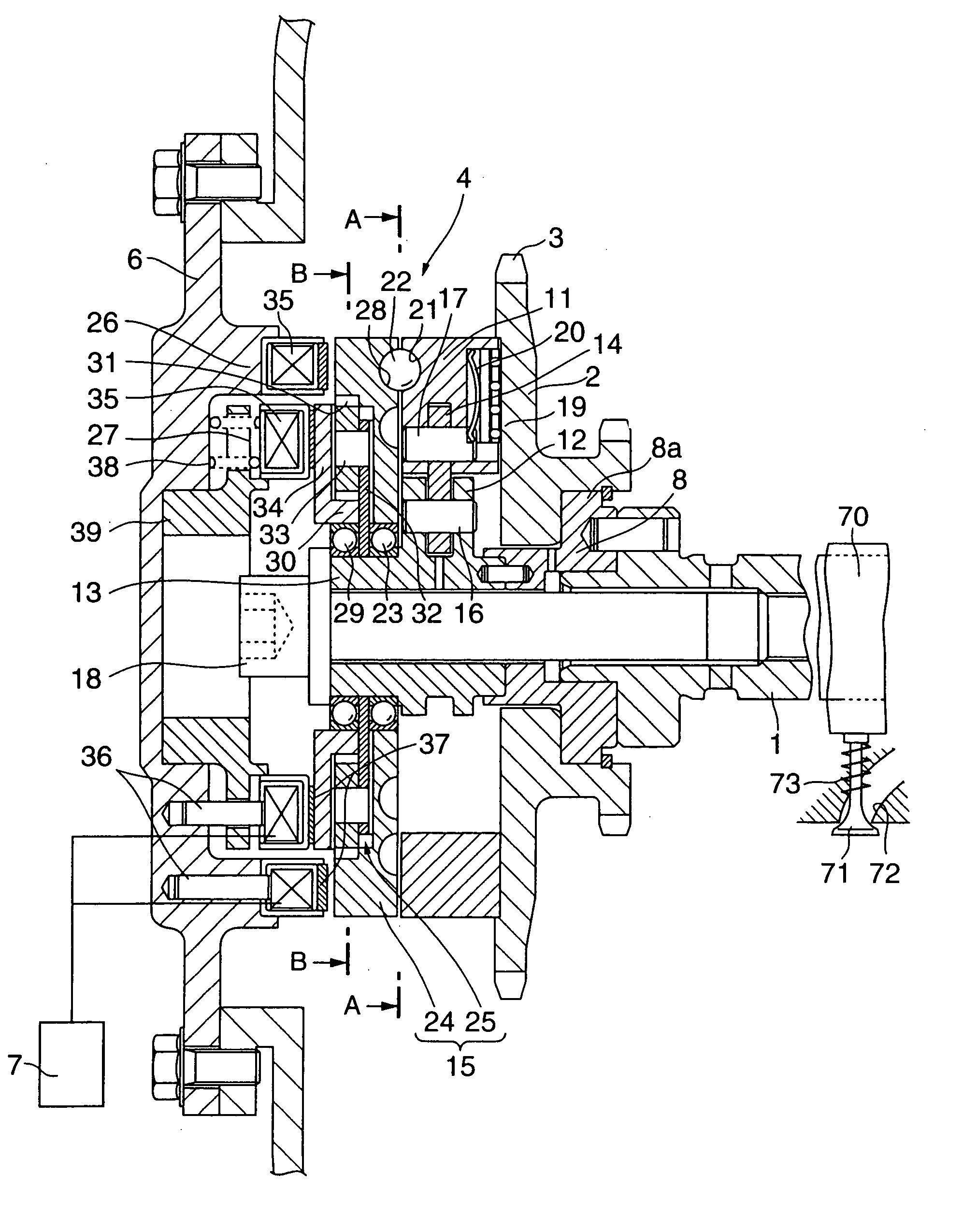
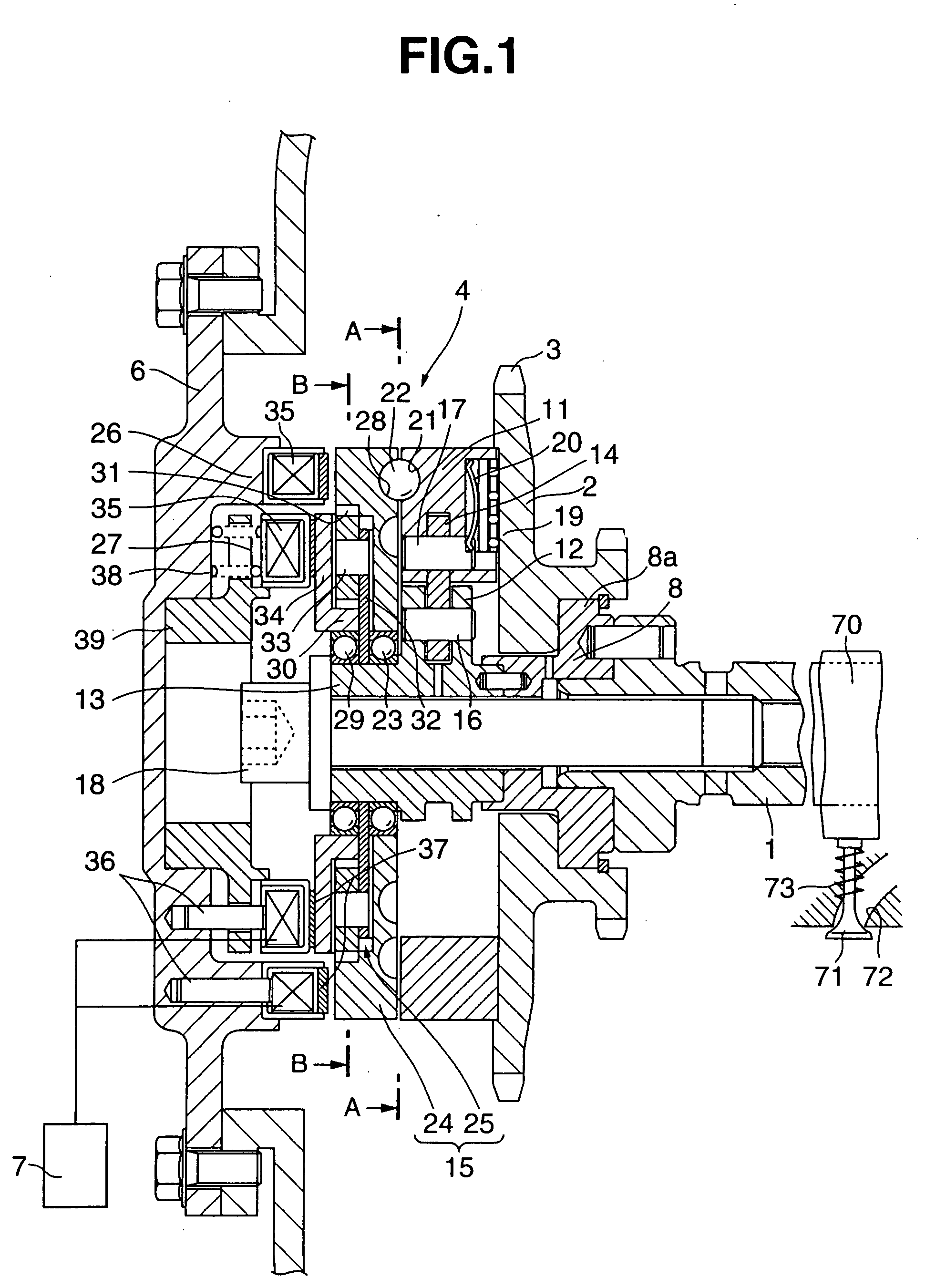
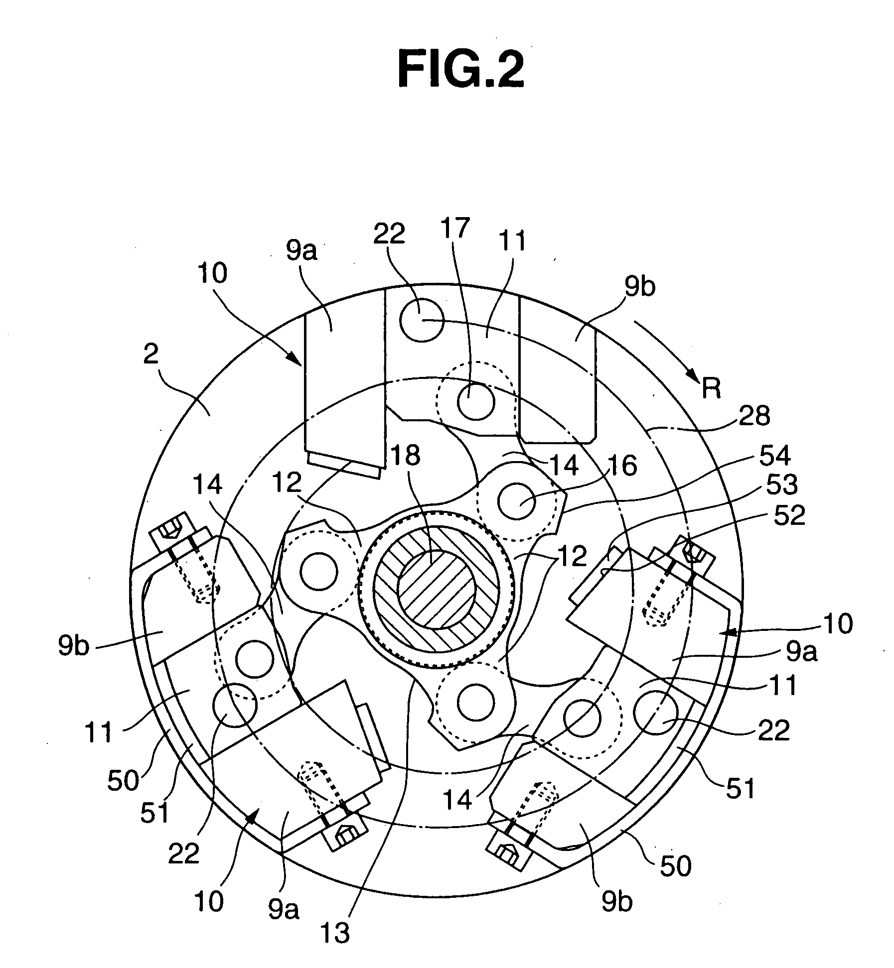
[0018] First of all, the device of the first embodiment is described hereunder in reference to FIGS. 1 through 5. The valve timing control device of the first embodiment is exemplified in an intake valve of an internal combustion engine, but, in the same manner as the intake valve side, the device of the embodiment can be applied to an exhaust valve.

[0019] The valve timing control device includes an engine valve 71 provided at an intake port 72 of the engine to open and close the intake port 72, a valve spring 73 biasing the engine valve 71 in a direction intake port 72 closes, a camshaft 1 rotatably supported on a cylinder head of the engine and having a cam 70 formed on an outer periphery thereof and used to drive the intake valve, a disc-shaped driving plate 2 (a driving rotational member) rotatably installed on a front end of camshaft 1, a timing sprocket 3 formed on driving plate...


PUM


Abstract

A valve timing control device includes a drive pulley driven by a crankshaft of an engine, and a driven camshaft. The camshaft has a cam that serves to open and close an intake port. An engine valve is spring-loaded by a valve spring, whereas the cam opens or closes the engine valve against the bias of the spring. Torque is transmittable between the drive pulley and the camshaft, and a rotation angle adjusting mechanism is provided therebetween. The rotation angle adjusting mechanism has a movable operating member being movable in a substantially radial direction.

Description

RELATED APPLICATIONS [0001] This application is a divisional of U.S. application Ser. No. 10 / 765,105, filed Jan. 28, 2004, which is a continuation of U.S. application Ser. No. 09 / 959,193, filed Oct. 19, 2001, now U.S. Pat. No. 6,832,585, which claims priority from PCT / JP2001 / 00576, filed Jan. 29, 2001, and published as WO 2002 / 061241. The entire contents of each of the aforementioned applications are incorporated herein by reference.TECHNICAL FIELD [0002] The invention relates to a valve timing control device for an internal combustion engine which variably controls valve-open and valve-closure timings of intake-port side and exhaust-port side engine valves, depending upon engine operating conditions. BACKGROUND ART [0003] A conventional valve timing control device has been disclosed in Japanese Patent Provisional Publication No. 10-153104. [0004] Briefly speaking, in this conventional valve timing control device, a timing pulley (a driving rotational member), driven by a crankshaft...

Claims


Application Information

Patent Timeline
Patent Type & Authority Applications(United States)
IPC IPC(8): F01L1/34F01L1/344F01L1/352F01L1/356
CPCF01L1/34F01L1/34409F01L1/352Y10T74/2102F01L2101/00F01L2105/00F01L1/356F01L2301/00F01L2305/00
Inventor WATANABE, MASAHIKO
Owner HITACHI LTD
Why Eureka
Try Eureka