
Anterior cervical plating system and method

a cervical plate and anterior cervical technology, applied in the field of anterior cervical plate and system, can solve the problems of compromising the load bearing and support capacity of the spine, affecting the etc., to achieve the effect of avoiding stress shielding, promoting fusion and incorporation of the graft, and avoiding stress shielding

Inactive Publication Date: 2007-08-30
WARSAW ORTHOPEDIC INC
View PDF4 Cites 47 Cited by
  • Summary
  • Abstract
  • Description
  • Claims
  • Application Information

AI Technical Summary

Benefits of technology

The present invention provides a system for anterior fixation of the spine using an elongated fixation plate with bone engaging fasteners that promote fusion and incorporation of a graft or implant into the spinal column portion. The plate has a central axis and is designed to be secured to a first vertebra and a second vertebra. The system allows for pre-load and continuous loading of the graft or implant, promoting bone growth and fusion. The plate has a first end with a pair of holes and a second end with a pair of slots, through which the bone engaging fasteners extend to secure the plate to the vertebrae. The system also includes a retainer assembly for the plate. The technical effects of the invention include improved spinal column stability, reduced stress-shielding, and promotion of bone growth and fusion.

Problems solved by technology

As with any bony structure, the spine is subject to various pathologies that compromise its load bearing and support capabilities.
This is particularly important in such procedures that relate to the cervical spine because the complications can be very devastating, such as injury to the brain stem, spinal cord, or vertebral arteries.

Method used


Image

  • Anterior cervical plating system and method
  • Anterior cervical plating system and method
  • Anterior cervical plating system and method

Examples


Embodiment Construction

[0045] For the purposes of promoting an understanding of the principles of the invention, reference will now be made to the embodiments illustrated in the drawings and specific language will be used to describe the same. It will nevertheless be understood that no limitation of the scope of the invention is thereby intended. Any alterations and further modifications in the illustrated devices, and any further applications of the principles of the invention as illustrated herein, are contemplated as would normally occur to one skilled in the art to which the invention relates.

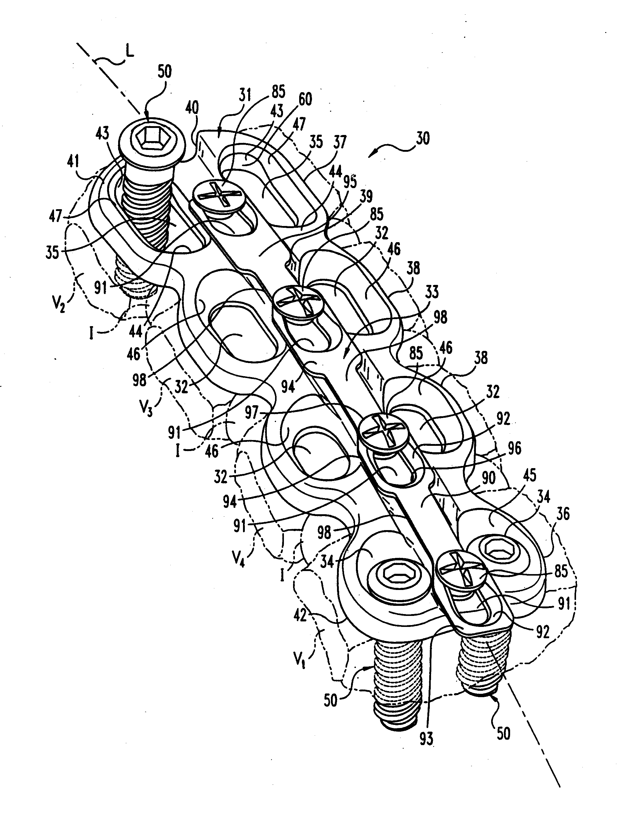
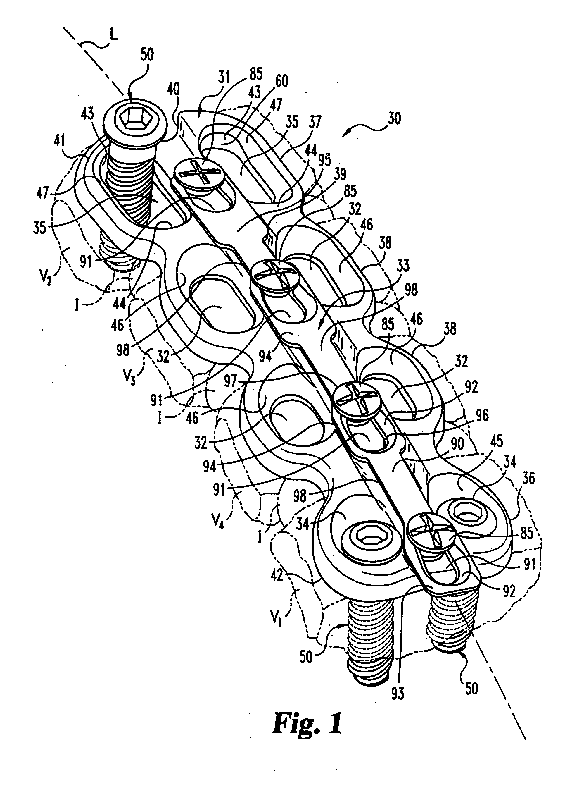
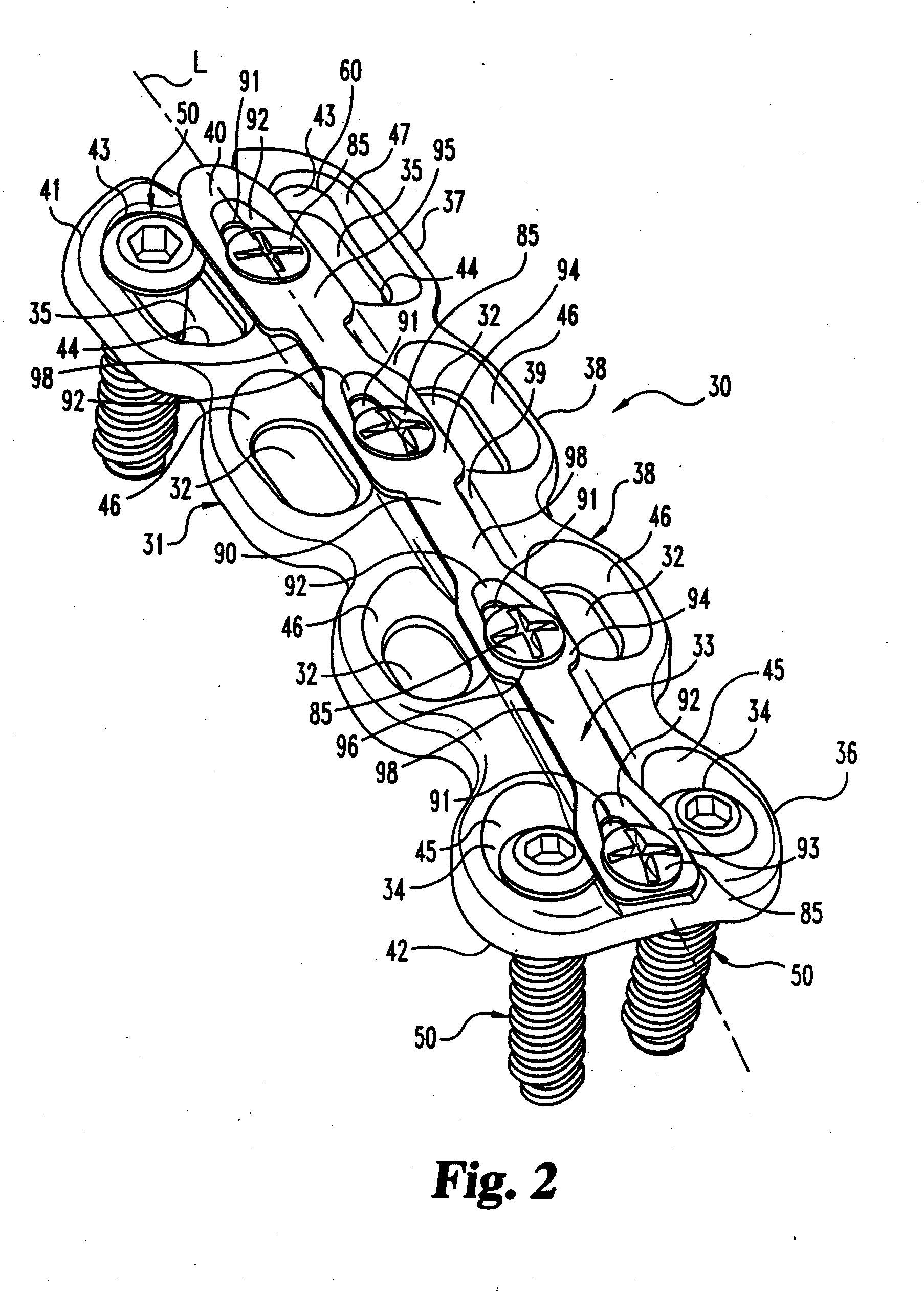
[0046] A plating system 30 having application in an anterior approach to the cervical spine is depicted in FIGS. 1-3. The portion of the spine is shown schematically in FIG. 1 to include a first vertebra V1, a second vertebra V2, and intermediate vertebrae V3 and V4. Preferably, first vertebra V1 is the inferior or bottom vertebra in the portion of the spinal column and the second vertebra V2 is the superior or ...


PUM


Abstract

The present invention is directed to a system for anterior fixation of the spine that utilizes an elongated fixation plate. The plating system stabilizes the spine and promotes fusion and incorporation of a graft or implant in a portion of the spinal column. In one aspect of the invention, the fixation plate has a first end with a pair of holes. Bone screws extend through the holes to rigidly secure the plate to a first vertebra. The second end of the plate is provided with a pair of slots through which bone screws extend for engagement with a second vertebra. The screws extending through the slots are translatable in the slot to maintain compression of the spinal column portion. The plating system includes a retainer assembly that prevents screw back out. Methods and instruments relating to the plating system are also described.

Description

CROSS REFERENCE TO RELATED APPLICATIONS [0001] This application is a continuation of U.S. application Ser. No. 10 / 134,463, filed Apr. 30, 2002, which is a continuation of U.S. application Ser. No. 09 / 417,402, filed Oct. 13, 1999, now U.S. Pat. No. 6,533,786, both of which are hereby incorporated by reference in their entirety.BACKGROUND OF THE INVENTION [0002] The present invention relates generally to the field of instrumentation and systems for the spine, and more particularly to instrumentation and systems for use in treatment of various pathologies of the cervical spine. [0003] As with any bony structure, the spine is subject to various pathologies that compromise its load bearing and support capabilities. Such pathologies of the spine include, for example, degenerative diseases, the effects of tumors and, of course, fractures and dislocations attributable to physical trauma. Spinal surgeons have addressed these problems using a wide variety of instrumentation in a broad range o...

Claims


Application Information

Patent Timeline
Patent Type & Authority Applications(United States)
IPC IPC(8): A61B17/58A61B17/56A61B17/70A61B17/80A61B17/88
CPCA61B17/1728A61B17/7059A61B17/8014A61B17/1757A61B17/8042A61B17/808A61B17/8866A61B17/8019
Inventor NEEDHAM, DUSTY ANNAPOYNER, JEFFREY WADEHERKOWITZ, HARRY N.ZDEBLICK, THOMAS A.
Owner WARSAW ORTHOPEDIC INC
Learn More