
Surgical microwave ablation assembly

a technology of ablation assembly and surgical technique, which is applied in the field of surgical microwave ablation assembly and improved ablation devices, can solve the problems of difficult ablation of targeted tissues

Inactive Publication Date: 2007-08-30
MAQUET CARDIOVASCULAR LLC
View PDF99 Cites 219 Cited by
  • Summary
  • Abstract
  • Description
  • Claims
  • Application Information

AI Technical Summary

Problems solved by technology

In some ablation procedures, however, the ablation of the targeted tissues may be difficult because of their location or the presence of physiological obstacle.

Method used


Image

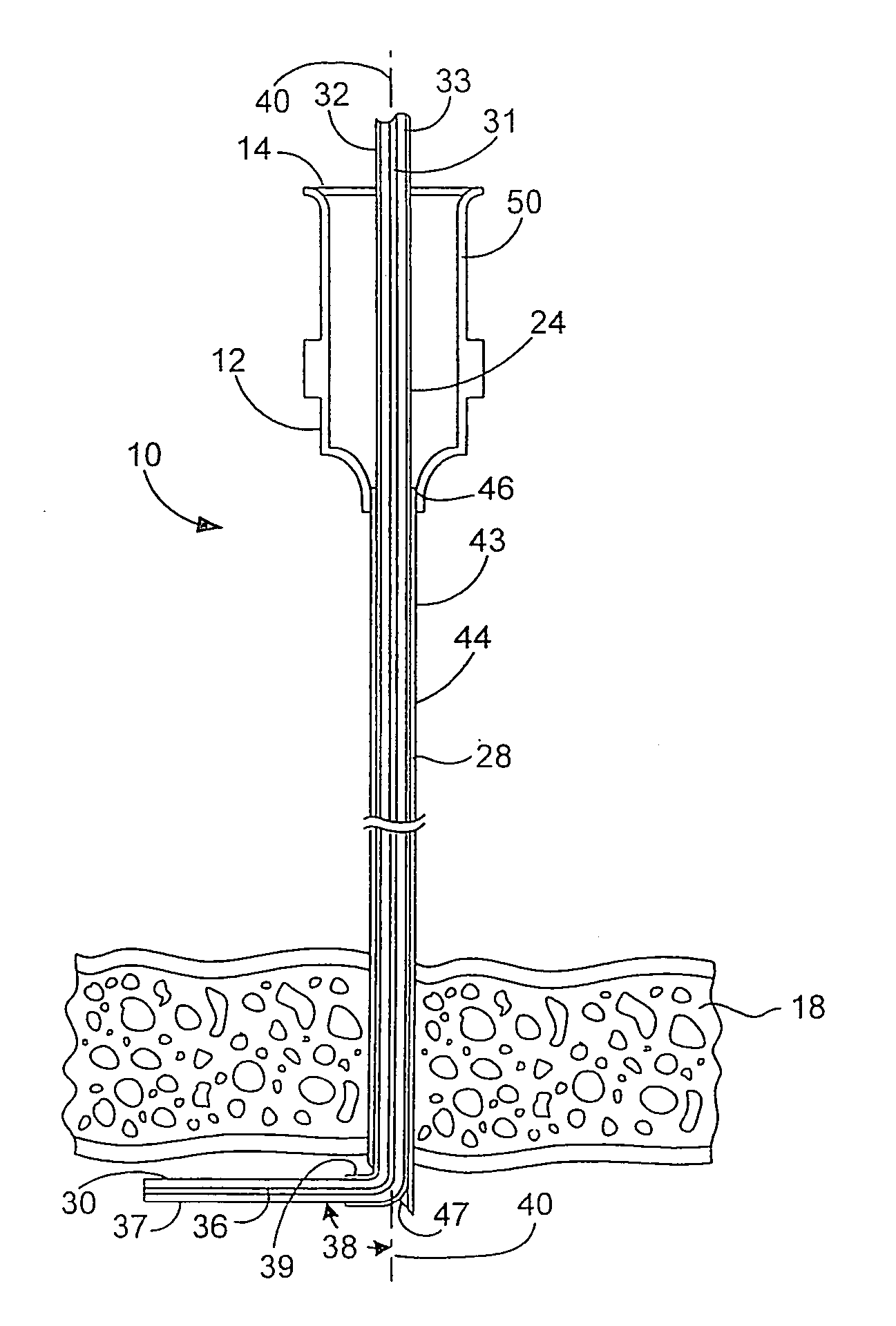
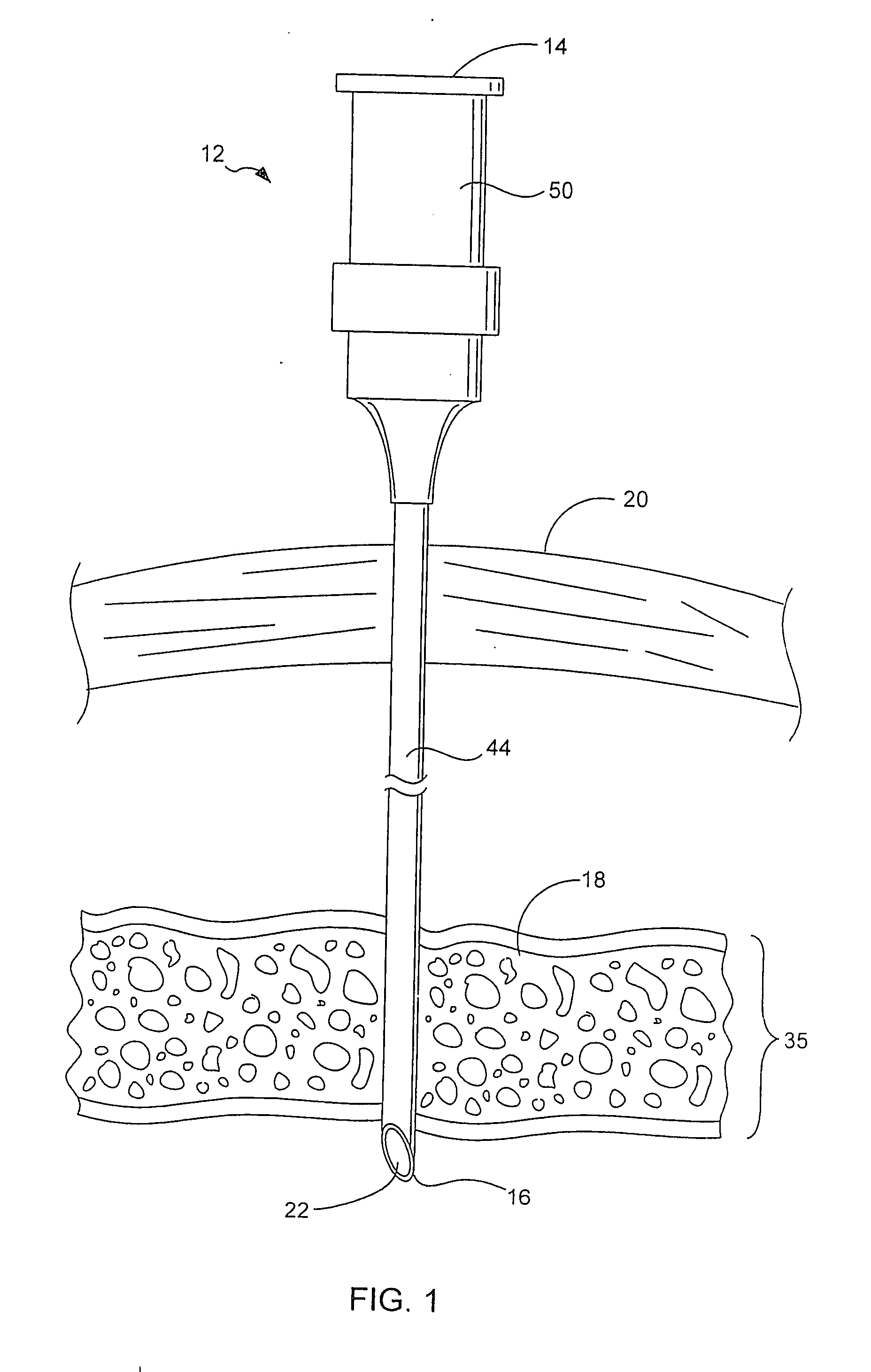
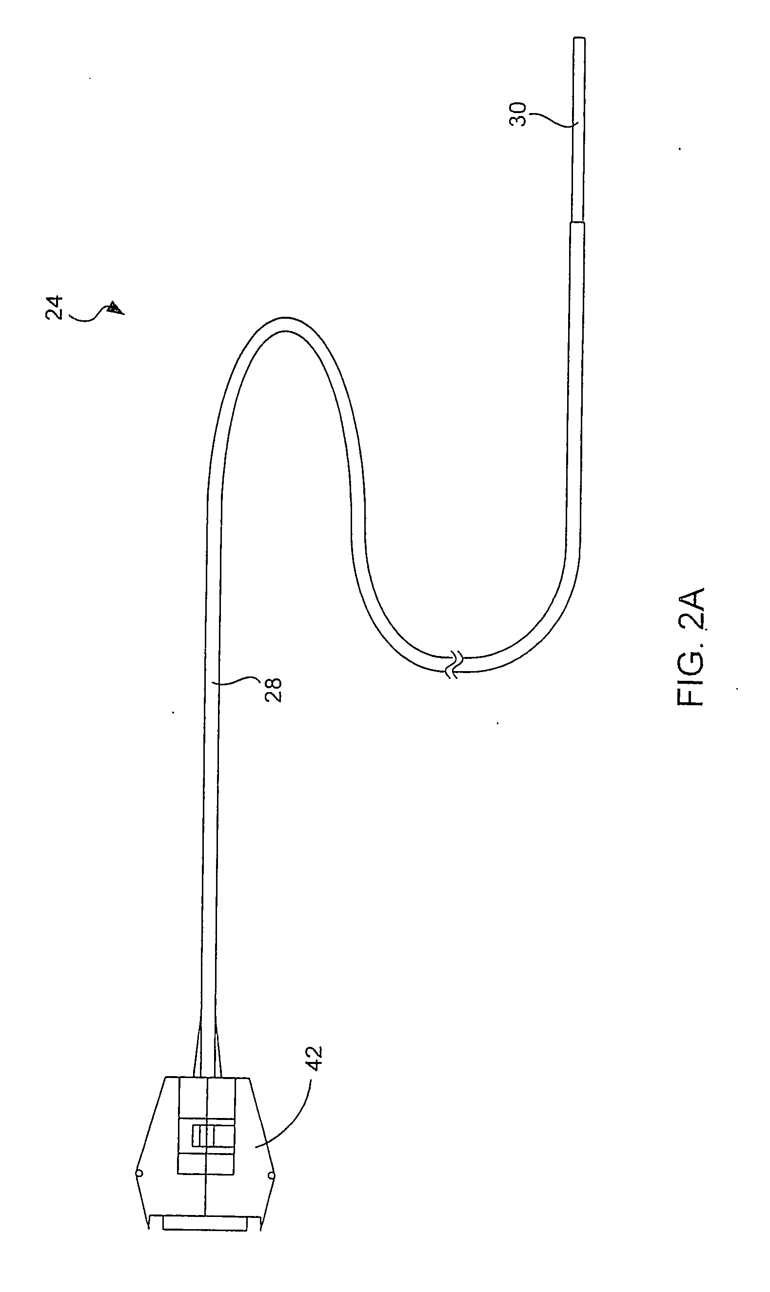
  • Surgical microwave ablation assembly
  • Surgical microwave ablation assembly
  • Surgical microwave ablation assembly

Examples


Embodiment Construction

[0049] The present invention will now be described in detail with reference to a few preferred embodiments thereof and as illustrated in the accompanying drawings. In the following description, numerous specific details are set forth in order to provide a thorough understanding of the present invention. It will be apparent, however, to one skilled in the art, that the present invention may be practiced without some or all of these specific details. In other instances, well known process steps have not been described in detail in order not to unnecessarily obscure the present invention.

[0050] The present invention provides an ablation assembly that is capable of ablating tissues inside the cavity of an organ (or duct). More specifically, the present invention provides an ablation assembly that is capable of producing lesions along an interior wall of an organ. The ablation assembly generally includes an ablative energy source and an ablative energy delivery device coupled to the abl...


PUM


Abstract

An ablation assembly capable of ablating tissues inside the cavity of an organ is disclosed. The ablation assembly generally includes an ablative energy source and an ablative energy delivery device coupled to the ablative energy source. The ablative energy delivery device is configured for delivering ablative energy sufficiently strong to cause tissue ablation. The ablative energy delivery device generally includes a penetration end adapted to penetrate through a wall of an organ and an angular component that is used to position the device inside the organ after the device has penetrated through the wall of the organ.

Description

BACKGROUND OF THE INVENTION [0001] The present invention relates to apparatus and methods for ablating biological tissues. More particularly, the present invention relates to improved ablation devices that are capable of penetrating through bodily organs. [0002] Since their introduction at the end of the 80's, medical ablation devices have become a standard tool for surgeons and electrophysiologists. For example, ablation devices utilizing DC shock, radio frequency (RF) current, ultrasound, microwave, direct heat, cryothermy or lasers have been introduced and employed to various degrees to ablate biological tissues. In some ablation procedures, however, the ablation of the targeted tissues may be difficult because of their location or the presence of physiological obstacle. For example, in some coronary applications where the ablation lines are done epicardially, the epicardium may be covered by layers of fat that can prohibit the lesion formation in the myocardial tissue. [0003] Ca...

Claims


Application Information

Patent Timeline
Patent Type & Authority Applications(United States)
IPC IPC(8): A61B18/18A61B17/00A61B18/14
CPCA61B18/1477A61B18/18A61B18/1815A61B2018/1861A61B2018/00357A61B2018/1425A61B2018/183A61B2017/00243
Inventor MODY, DINESHBERUBE, DANYNORRIS, NANCYCHIN, ROY
Owner MAQUET CARDIOVASCULAR LLC
Learn More