
Sheet-transporting apparatus

Inactive Publication Date: 2007-08-30
HEIDELBERGER DRUCKMASHINEN AG
View PDF8 Cites 0 Cited by
  • Summary
  • Abstract
  • Description
  • Claims
  • Application Information

AI Technical Summary

Benefits of technology

[0007] A particular advantage of the invention is the fact that the leaf springs of the gripper are disposed such that imaginary extensions of the leaf springs intersect at a point on a region of a straight line which passes through the gripper tip and the axis of the gripper shaft. The region of the straight line is located on the far side of the stretch between the gripper tip and the gripper-shaft axis. This gives rise to a virtual point of rotation for the gripper tip at this point relative to the gripper shaft. However, since it is additionally the case with this configuration that there is a only a slight change in the distance between this point and the point at which the gripper tip meets up with the gripper support in the event of “over-pressing”, the result is just a very small amount of tolerable gripper shifting. A measure provided for adjusting this point can reduce the “shifting” to more or less zero.
[0008] This measure makes it possible, while maintaining the stability of the gripper, to achieve an extraordinarily favorable mass moment of inertia and, at the same time, to prevent undesired “shifting” of the gripper tip in relation to the gripper supports.
[0009] In an advantageous configuration, the gripper has a low-mass thin-walled sheet-metal housing. This makes it possible to keep the weight of the moving masses low. The sheet-metal housing has flexible, resiliently elastic regions, e.g. leaf springs, which allow resilient deflection of the gripper tip.
[0010] In an advantageous configuration, for the purpose of fastening the gripper tip on the gripper shaft, the low-mass sheet-metal housing is connected to the gripper shaft by a clamping component.
[0011] The configuration of the leaf springs constitutes a significant advantage of the invention.
[0012] A significant advantage of the configuration is that it cuts back considerably on the amount of installation space required, since the sheet-metal part can be formed around the gripper shaft, which is as stiff as possible. Furthermore, the gripper shaft may be dimensioned to be large enough for it also to be possible to arrange a torsion spring in the interior of the gripper shaft in order to generate restoring forces of known control rollers which are provided.

Problems solved by technology

However, since it is additionally the case with this configuration that there is a only a slight change in the distance between this point and the point at which the gripper tip meets up with the gripper support in the event of “over-pressing”, the result is just a very small amount of tolerable gripper shifting.

Method used


Image

  • Sheet-transporting apparatus
  • Sheet-transporting apparatus
  • Sheet-transporting apparatus

Examples


Embodiment Construction

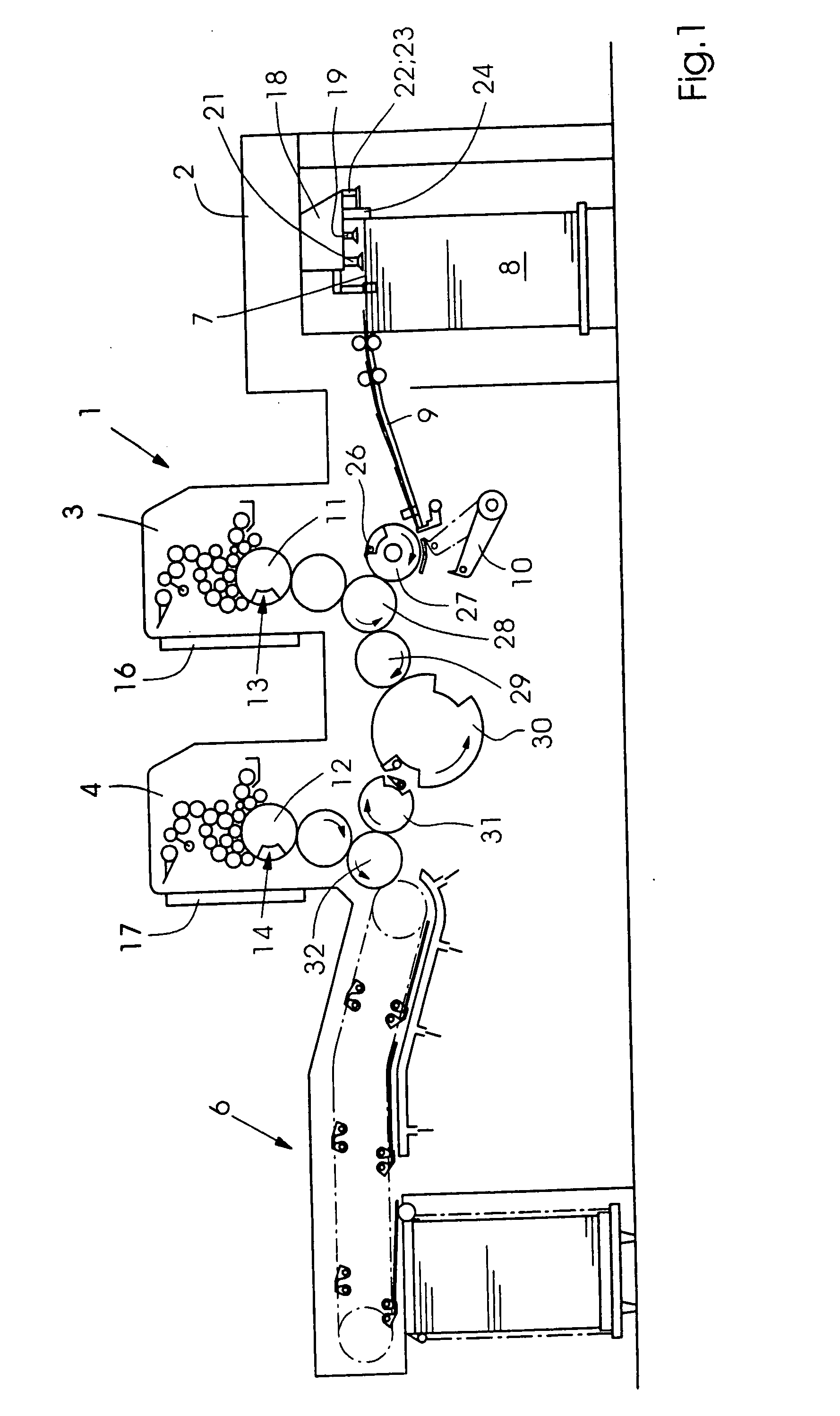
[0020] Referring now to the figures of the drawing in detail and first, particularly, to FIG. 1 thereof, there is shown a machine 1 which processes sheets 7, e.g. a printing machine 1, that has a feeder 2, at least one printing unit 3, 4 and a delivery 6. The sheets 7 are removed from a sheet stack 8 and fed separately or in imbricated form to the printing units 3 and 4 via a feed table 9. The printing units 3, 4 each contain, in a known manner, a plate cylinder 11, 12. The plate cylinders 11 and 12 each have a configuration 13, 14 for fastening flexible printing plates. Furthermore, each plate cylinder 11, 12 is assigned a configuration 16, 17 for semi-automatic or fully automatic printing-plate changeover.

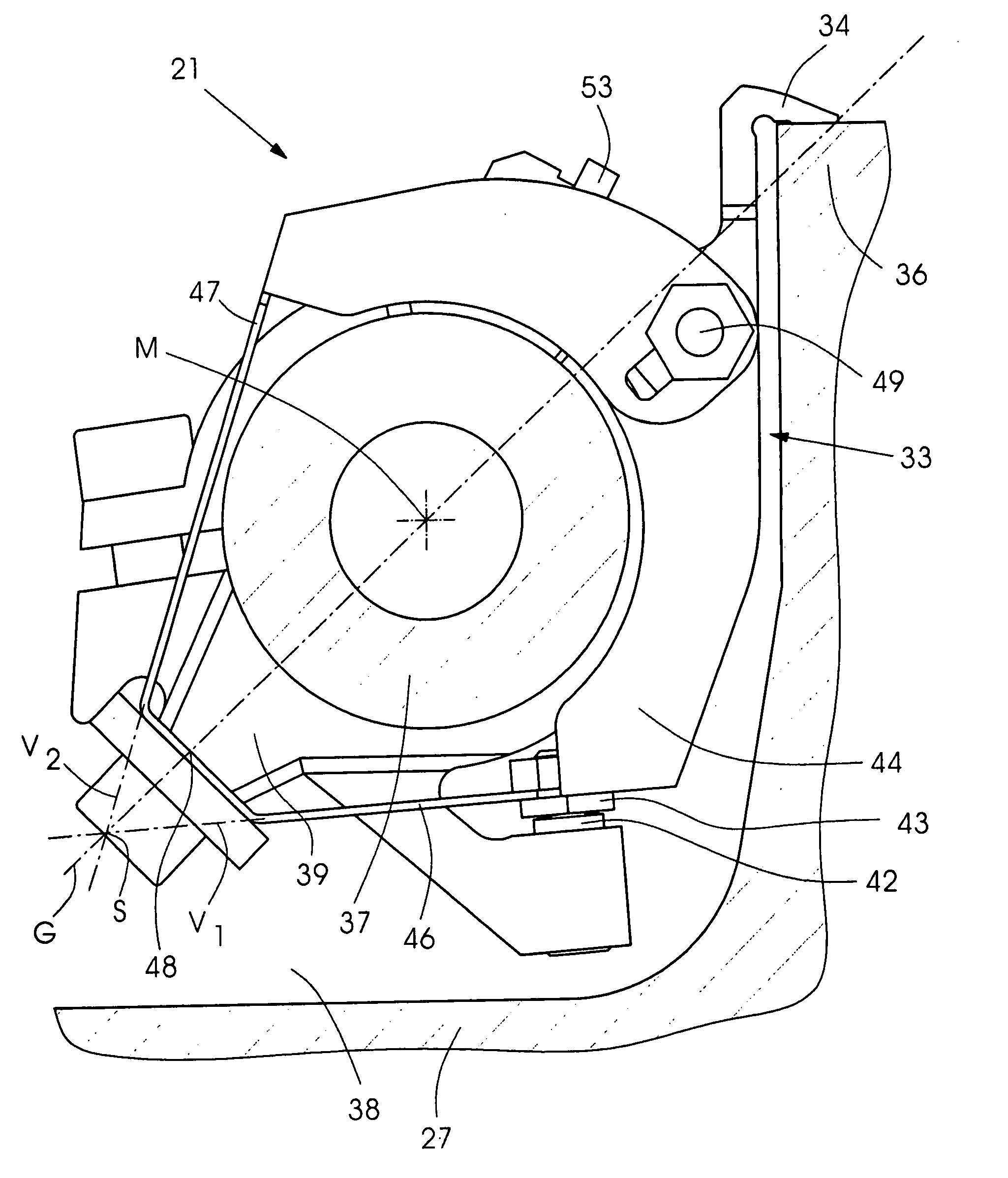
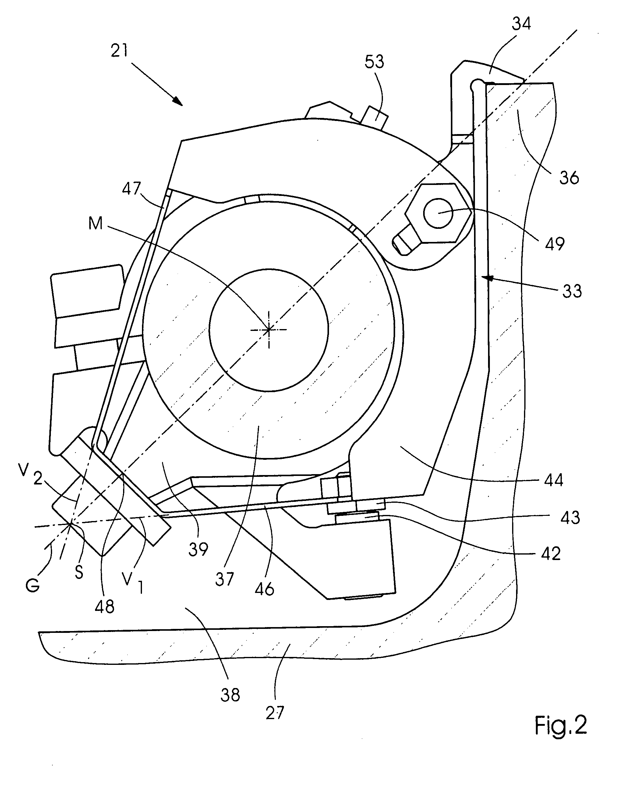
[0021] The sheet stack 8 rests on a stacking panel 10 which can be raised in a controlled manner. The sheets 7 are removed from the top side of the sheet stack 8 by a so-called suction head 18 which, inter alia, has a number of lifting and pull suckers 19, 21 for separating the ...


PUM


Abstract

In the case of a sheet-transporting gripper configuration in a sheet-processing machine, e.g. printing machine, it is provided that a low-mass gripper housing contains thin side walls enclosing a gripper shaft such that imaginary extensions of leaf springs provided intersect at a point on a straight line which passes through gripper tips and a gripper-shaft axis. The point of intersection is located on the far side of the gripper-shaft axis, as seen from the gripper tips.

Description

CROSS-REFERENCE TO RELATED APPLICATION [0001] This application claims the priority, under 35 U.S.C. §119, of German application DE 10 2006 007 725.3, filed Feb. 20, 2006; the prior application is herewith incorporated by reference in its entirety. BACKGROUND OF THE INVENTION Field of the Invention [0002] The invention relates to a sheet-transporting gripper in a sheet-processing machine, in particular a printing machine. [0003] Published, non-prosecuted German patent application DE 35 29 612 A1, corresponding to U.S. Pat. No. 4,719,854, discloses, for example, a sheet-transporting gripper configuration provided in a cylindrical channel of a sheet-transporting cylinder. The gripper configuration has a gripper finger which is mounted on a pivotable shaft and interacts with a cylinder-mounted gripper support. In order to provide for play-free and thus displacement-free mounting, the gripper finger is fastened on a gripper shaft by two leaf springs and a clamping component. Imaginary ex...

Claims


Application Information

Patent Timeline
IPC IPC(8): B41F21/10
CPCB41F21/05B41F21/14B41F21/104B41F21/10
Inventor MUTSCHALL, STEFAN
Owner HEIDELBERGER DRUCKMASHINEN AG
Learn More