
Trocar seal system

a seal system and trocar technology, applied in the field of seal systems, can solve the problems of difficulty in inserting the difficulty of insertion and advancing surgical instruments through the seal unit, and the level of force needed to insert and advance instruments, etc., to achieve the effect of reducing friction

Active Publication Date: 2007-08-23
TYCO HEALTHCARE GRP LP
View PDF102 Cites 20 Cited by
  • Summary
  • Abstract
  • Description
  • Claims
  • Application Information

AI Technical Summary

Benefits of technology

The present invention provides a seal assembly for surgical instruments that can be used to receive and seal elongated surgical instruments. The seal assembly includes a body with an opening for the instrument, a resilient seal member with an aperture that contacts the instrument, and a fabric layer. The seal member can also have a coating to reduce friction with the instrument. A ring member with a dampening element can also be included. The technical effect of this invention is to provide a reliable and effective seal for surgical instruments, which can help to prevent leakage and facilitate the use of instruments in surgical procedures.

Problems solved by technology

Moreover, endoscopic procedures often require the surgeon to act on organs, tissues, and vessels far removed from the incision, thereby requiring that any instruments used in such procedures be relatively long and narrow.
A disadvantage of several known seal systems for cannulas concerns the difficulty encountered in inserting and advancing the surgical instrument through the seal unit.
As a consequence of these design considerations, the level of force needed to insert and advance the instrument through the seal aperture is increased, thereby requiring awkward maneuvering on the surgeon's behalf to appropriately position the instrument for the desired surgery.
Moreover, known seal systems are generally ineffectual in accommodating instruments of differing diameter while maintaining acceptable insertion forces and facilitating the range of desired surgical manipulations, e.g., angular instrument movements and specimen removal.

Method used


Image

  • Trocar seal system
  • Trocar seal system
  • Trocar seal system

Examples


Embodiment Construction

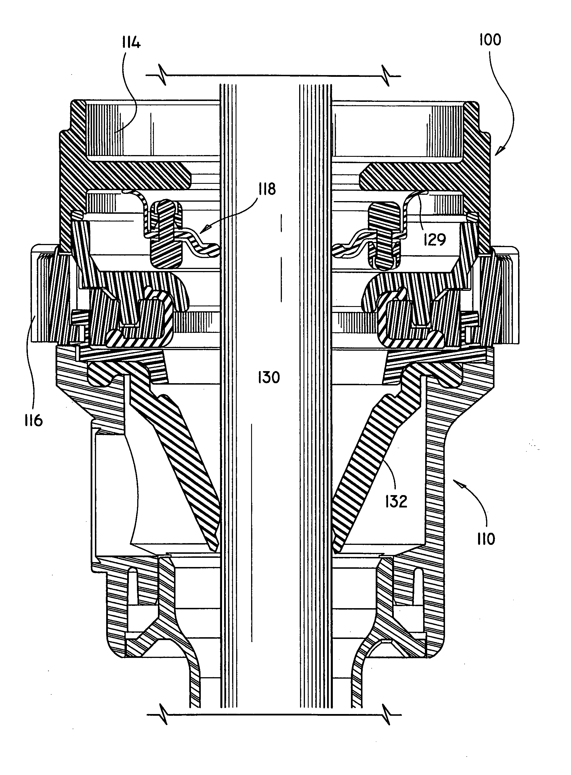
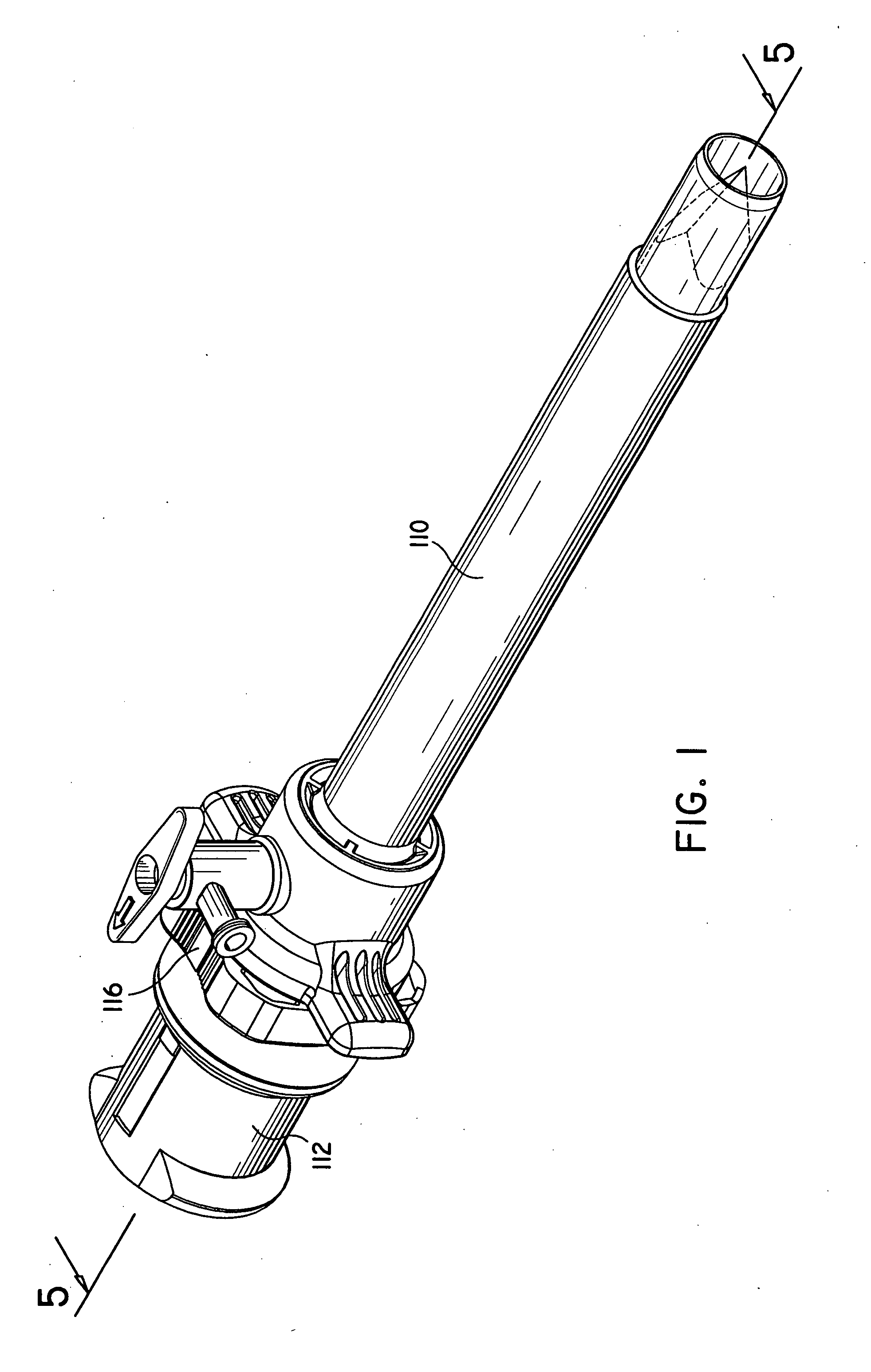
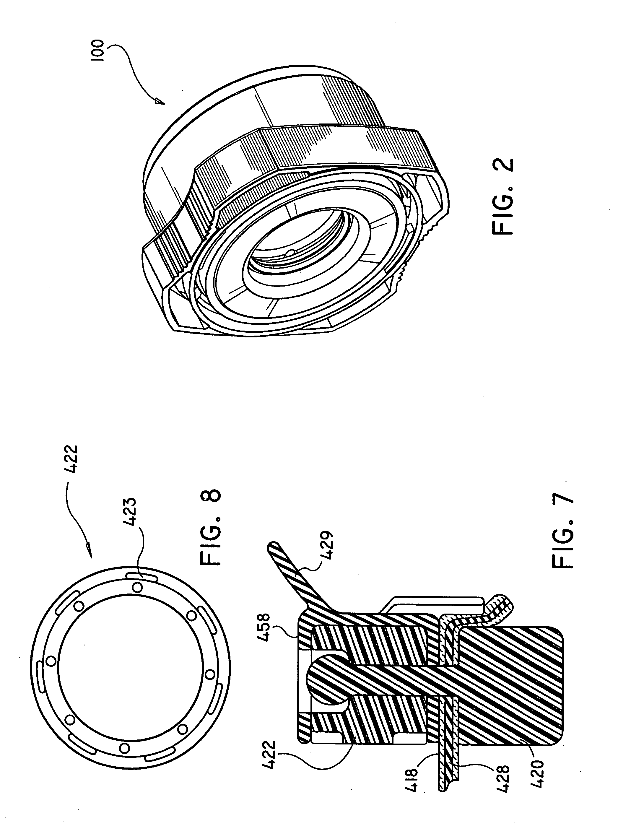
[0027] Referring now in detail to the drawing figures in which like reference numerals identify similar or identical elements, a seal assembly of the present disclosure is illustrated in FIGS. 1-5, and is designated generally as seal assembly 100.

[0028] The presently disclosed seal assembly embodiments contemplate the introduction of various types of surgical instruments adapted for insertion through an elongated trocar assembly. Examples of such instruments include clip appliers, graspers, dissectors, retractors, staplers, laser fibers, photographic devices, endoscopes and laparoscopes, tubes, and the like. Such instruments are collectively referred to herein as “instruments”.

[0029] Referring to FIGS. 1 and 2, seal assembly 100 is used in combination with a conventional trocar assembly which includes a cannula assembly 110 and a trocar obturator 112. Examples of trocar assemblies in which the present seal assembly may be utilized are disclosed in U.S. Pat. No. 5,603,702 which iss...


PUM


Abstract

A seal assembly is provided for reception of an elongated surgical instrument, which comprises a body having at least one opening configured and dimensioned to permit entry of an elongated surgical instrument and defining a central longitudinal axis; a seal member formed of a resilient material and defining an aperture therein, the aperture being configured and dimensioned such that insertion of the surgical instrument into the aperture causes the resilient material defining the aperture to resiliently contact the outer surface of the surgical instrument in a substantially fluid tight manner, the seal member further including a peripheral flange element which contacts a surface of the body to form a contact seal therewith; and a fabric layer juxtaposed relative to the resilient material. The seal assembly may further include a coating applied to the seal member to reduce friction between the seal member and surgical instrumentation inserted therein. The coating is preferably a hydrocyclosiloxane membrane prepared by plasma polymerization process.

Description

BACKGROUND [0001] 1. Technical Field [0002] The present disclosure relates to seal systems of the type adapted to allow the introduction of a surgical instrument into a patient's body. In particular, the disclosure relates to a seal system to be used in combination with a cannula assembly where the cannula assembly is intended for insertion into a patient's body and an instrument is inserted into the patient's body through the cannula. [0003] 2. Background of Related Art [0004] Laparoscopic procedures are performed in the interior of the abdomen through a small incision, e.g., through narrow endoscopic tubes or cannulas inserted through a small entrance incision in the skin. Minimally invasive procedures are performed elsewhere in the body, e.g., in the chest, and are often generally referred to as “endoscopic” procedures. Minimally invasive or endoscopic procedures generally require that any instrumentation inserted into the body be sealed, i.e. provisions must be made to ensure th...

Claims


Application Information

Patent Timeline
Patent Type & Authority Applications(United States)
IPC IPC(8): A61M39/02F16K15/00A61M25/01A61B17/34A61M39/06F16K15/14
CPCA61B17/3462A61B17/3498A61B2017/00526A61B2017/3464A61M39/06A61M39/0606F16K15/147A61M2039/0626A61M2039/0633A61M2039/0646A61M2039/0653A61M2039/0673A61M2039/0686A61M39/0613Y10T137/87804Y10T137/788F16K15/144
Inventor RACENET, DAVID C.STELLON, GENE A.VUMBACK, WILLIAM J.PASQUALUCCI, JOSEPH
Owner TYCO HEALTHCARE GRP LP
Learn More