
Railway bogie provided with a linear induction motor

a technology of inductors and bogies, which is applied in the direction of locomotives, transportation and packaging, propulsion railway systems, etc., can solve the problems of difficult precise adjustment of frame and inductors position, high acceleration level of bearings between beams and shafts, and inability to provide any resilient suspension, etc., to achieve small air gaps

Active Publication Date: 2007-08-23
BOMBARDIER TRANSPORTATION GMBH
View PDF11 Cites 9 Cited by
  • Summary
  • Abstract
  • Description
  • Claims
  • Application Information

AI Technical Summary

Benefits of technology

[0009] One object of the invention is to provide a bogie that allows very small air gaps between the linear inductor motor and the reaction rail.
[0014] two cross-members, each mounted on one of the pairs of left and right axle boxes via of left and right resilient mounting apparatus, the resilient mounting apparatus allowing limited pivoting movement of the cross-member about a transversal axis of rotation of the cross-member, and
[0019] Preferably, the linking apparatus includes at least two link members for connecting the linear induction motor to a first one of the two cross-members, the two link members being connected to the first cross-member at two locations laterally spaced apart on opposite sides of the centre point of the first cross member, and at least one link member for connecting the linear induction motor to the other cross-member. Thanks to this three-point leveling arrangement, height errors in the position of the linear induction motor can be easily corrected.
[0023] The adjustment mechanisms allow ready adjustment of the air gap between the reaction rail and the linear induction motor. More specifically, these mechanisms allow independent adjustment of the height, of the pitch angle and of the roll angle of the linear induction motor in relation to the reaction rail.

Problems solved by technology

However, precise adjustment of the position of the frame and inductors proves difficult, since each of the four screw and nut connections simultaneously influences the roll and pitch angles of the frame.
This arrangement does not provide any resilient suspension of the U-shape beams, and the bearings between the beams and the shaft experience high acceleration levels.
This motion, however, is not acceptable when the air gap is small.
Moreover, it is not possible to adjust the cross-level error of the linear inductor, i.e. the height difference between the left and right sides of the inductor, because the inductor is suspended from two points only spaced apart along the longitudinal centre axis of the vehicle.

Method used


Image

  • Railway bogie provided with a linear induction motor
  • Railway bogie provided with a linear induction motor
  • Railway bogie provided with a linear induction motor

Examples


Embodiment Construction

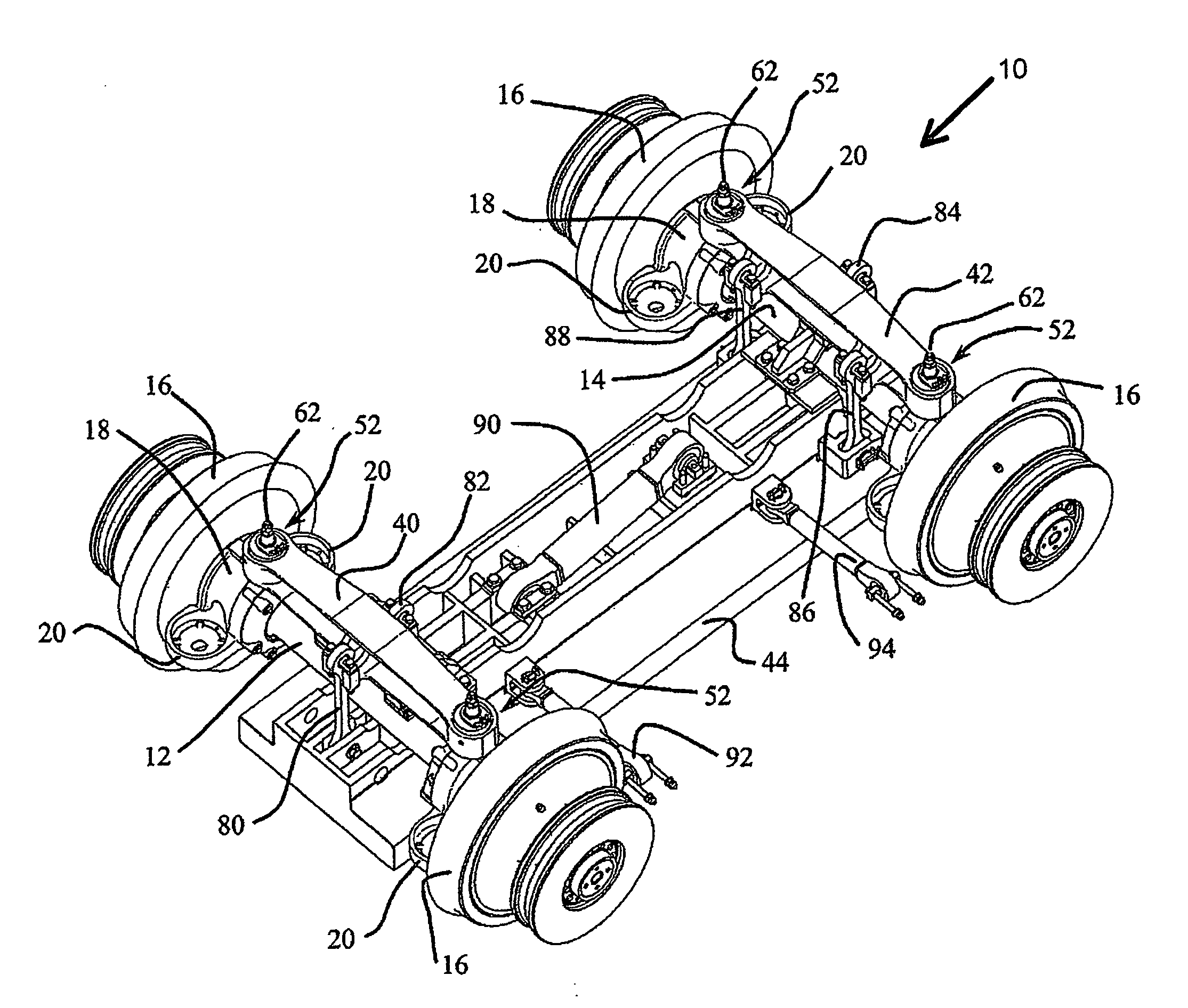
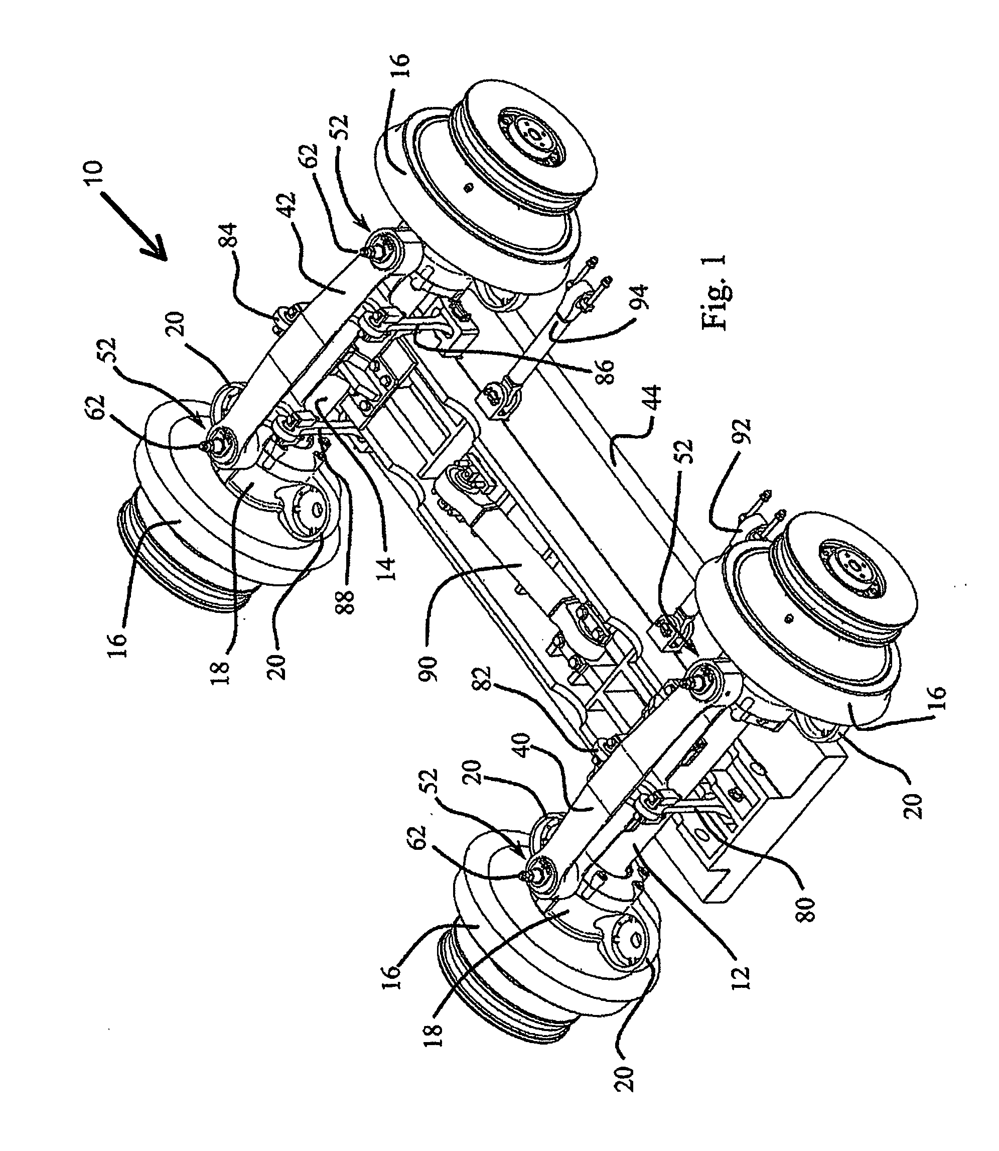
[0037] Referring to FIG. 1, the unsuspended part of a bogie 10 includes two wheel axles 12, 14 carrying the usual left and right track wheels 16. Each wheel axle 12, 14 is journalled in a pair of left and right axle boxes 18 located between the track wheels 16. Each axle box 18 is provided with front and rear pans 20 on which the lower end of a rubber spring 22 of the primary suspension seats is located.

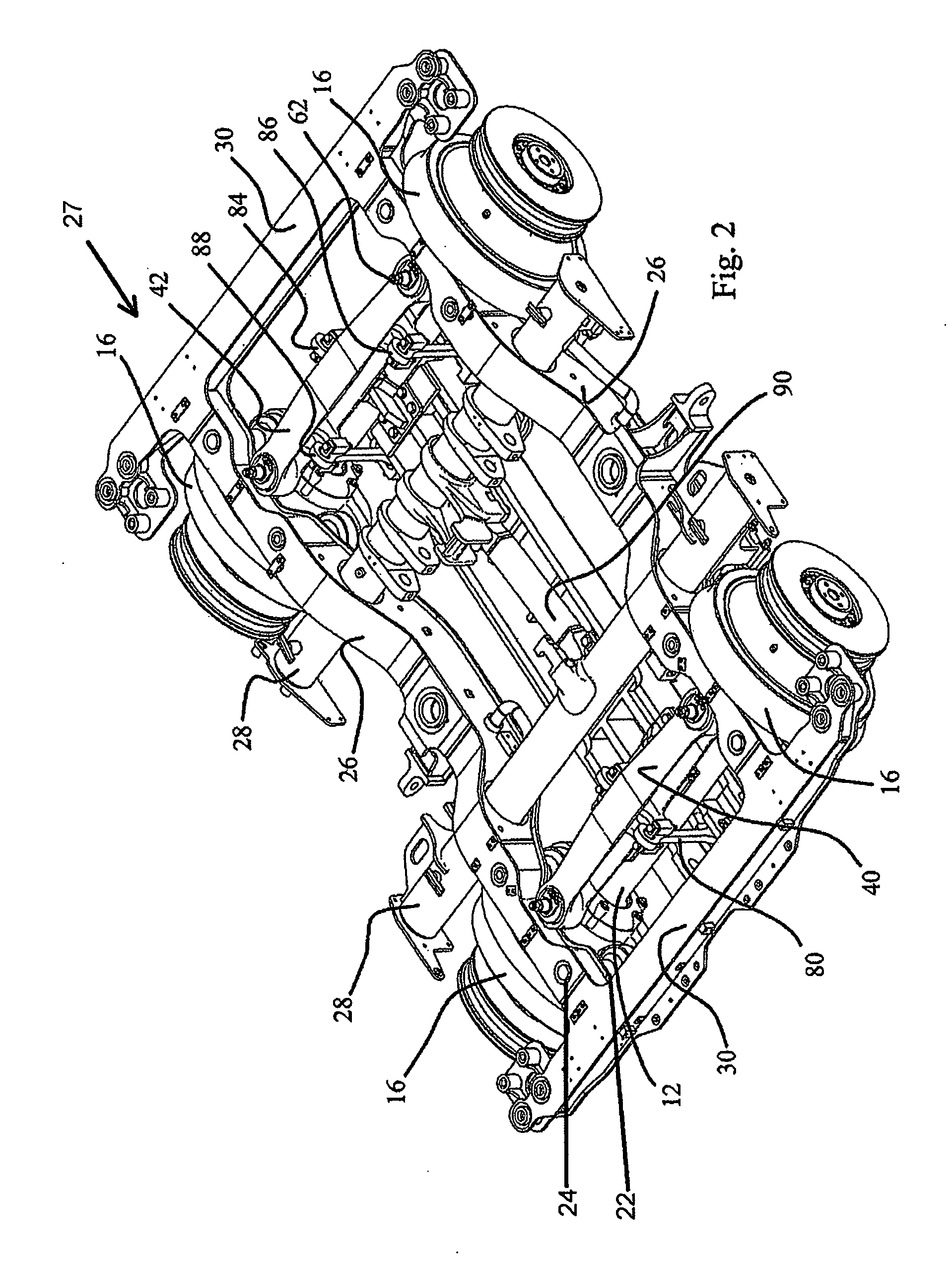
[0038] Each primary suspension spring 22 is screwed at its upper end to a spindle 24 that projects through a side bogie frame member 26 and is secured thereto, as illustrated in FIG. 2. The bogie frame 27 is provided with a pair of tubular transoms 28 and front and rear cross-members 30 welded to the side members 26. The vehicle body is supported on the bogie side members by an air spring assembly.

[0039] As shown in FIG. 2, the bogie is provided with a pair of cross-members 40, 42 for supporting the linear induction motor 44. Each cross-member 42, 44 extends above one of the wheel ...


PUM


Abstract

A railway bogie is provided with two cross-members for supporting a linear induction motor, mounted on the axle boxes via of resilient mounting apparatus allowing pivoting movement of each cross-member about a transversal axis of rotation. A system of five links is used to connect the linear induction motor to the cross-members. The links are located in such a way that the resultant of the vertical forces transmitted by the linear induction motor to each cross-member is located at a first centre position on the first transversal axis equidistant from the axle boxes. The mounting apparatus are further provided with height adjusters that allow adjustment of the height and cross level position of the linear induction motor.

Description

CROSS REFERENCE TO RELATED APPLICATIONS [0001] This application claims priority from European application number 05028323.3 filed on 23rd Dec. 2005, the contents of which are hereby incorporated by reference in their entirety. BACKGROUND OF THE INVENTION [0002] 1. Field of the Invention [0003] The invention relates to a railway bogie designed for propulsion by a linear induction motor, to an arrangement for mounting a linear induction motor to a bogie of a railway vehicle, in particular an arrangement equipped with an adjustment device for adjusting the height of the linear induction motor relative to a reaction rail. It also relates to a method for mounting a linear induction motor to a bogie of a railway vehicle, and to a method for adjusting the distance between the linear motor and the reaction rail. [0004] 2. Description of the Related Art [0005] Linear inductors consisting of field windings placed above one or several reaction rails and supplied with poly-phase current produci...

Claims


Application Information

Patent Timeline
IPC IPC(8): B60L13/00
CPCB60L13/035B60L2200/26B61B13/12
Inventor SEARANCKE, EDWIN JOSEPH
Owner BOMBARDIER TRANSPORTATION GMBH
Learn More