
Flash Memory Systems With Direct Data File Storage Utilizing Data Consolidation and Garbage Collection

a flash memory and data file technology, applied in the direction of memory architecture accessing/allocation, instruments, computing, etc., to achieve the effect of improving memory performance and avoiding consolidation

Active Publication Date: 2007-08-09
SANDISK TECH LLC
View PDF99 Cites 140 Cited by
  • Summary
  • Abstract
  • Description
  • Claims
  • Application Information

AI Technical Summary

Benefits of technology

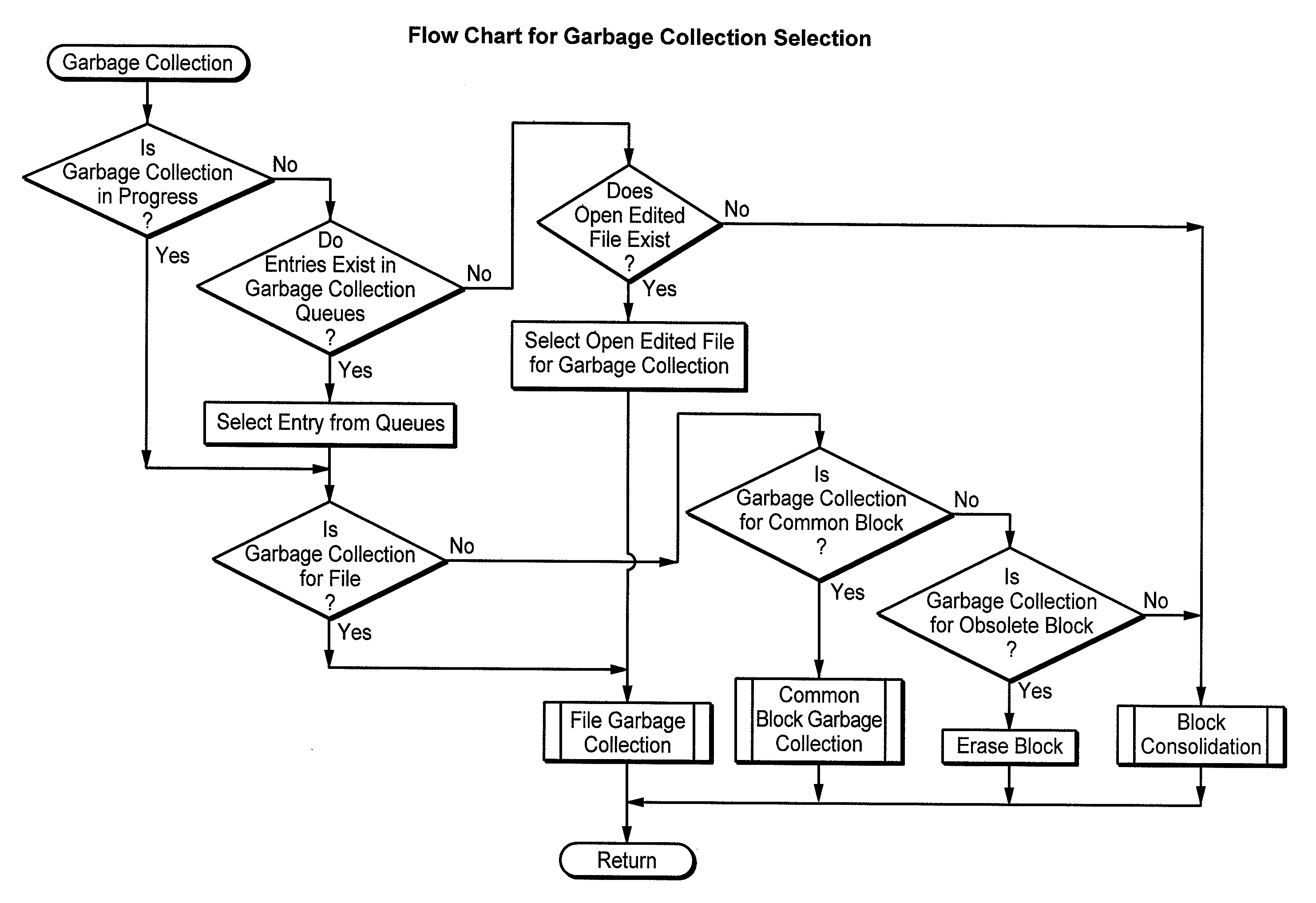
[0007] Rather than scheduling data consolidation of a newly written file right after the file is closed, data of a newly written file are maintained in the original blocks to which they were programmed after receipt from a host. This most commonly includes a block that is partially filled with the new data. Since it is not uncommon for a data file to be deleted or updated in a way that creates obsolete data, consolidation of the data of the partially filled block is postponed as long as possible after the file is closed. The file may be deleted without the need to relocate any data. Therefore, if the file is deleted or updated before such a consolidation becomes necessary, the consolidation is avoided. Such a consolidation can become necessary, as the memory becomes full, for there to be enough erased blocks for further programming of new data. But because the file based memory does not retain data files that have been deleted by the host, contrary to the case when a logical interface is used, the memory will usually have a sufficient number of erased blocks even though the consolidation is delayed. The time taken by the omitted consolidation is therefore saved, and the performance of the memory improved as a result.

Problems solved by technology

But because the file based memory does not retain data files that have been deleted by the host, contrary to the case when a logical interface is used, the memory will usually have a sufficient number of erased blocks even though the consolidation is delayed.

Method used


Image

  • Flash Memory Systems With Direct Data File Storage Utilizing Data Consolidation and Garbage Collection
  • Flash Memory Systems With Direct Data File Storage Utilizing Data Consolidation and Garbage Collection
  • Flash Memory Systems With Direct Data File Storage Utilizing Data Consolidation and Garbage Collection

Examples


Embodiment Construction

1. Direct Data File Platform

1.1 Summary

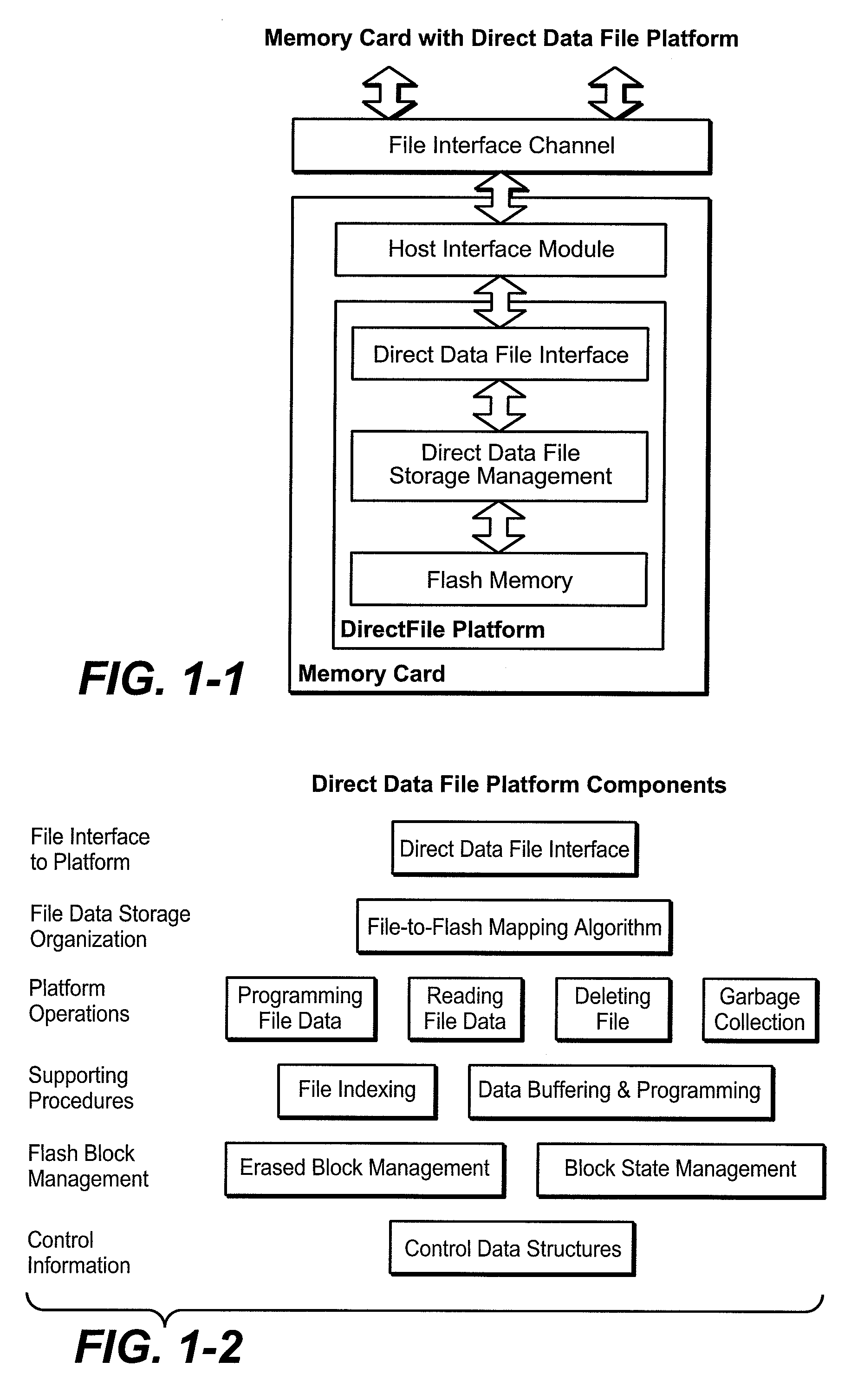
[0070] A memory card with a direct data file platform is illustrated in FIG. 1-1. The direct data file platform is a file-organized data storage device in which data is identified by filename and file offset address. It acts as the storage platform in a memory card that may incorporate functions other than data storage. File data is accessed in the platform by an external file interface channel.

[0071] The storage device has no logical addresses. Independent address spaces exist for each file, and the memory management algorithms organize data storage according to the file structure of the data. The data storage organization employed in the direct data file platform produces considerable improvement of operating characteristics, in comparison with those of a file storage device that integrates a conventional file system with conventional logically-blocked memory management.

1.2 Platform Components

[0072] The direct data file platform has t...


PUM


Abstract

Host system data files are written directly to a large erase block flash memory system with a unique identification of each file and offsets of data within the file but without the use of any intermediate logical addresses or a virtual address space for the memory. Directory information of where the files are stored in the memory is maintained within the memory system by its controller, rather than by the host.

Description

CROSS-REFERENCE TO RELATED APPLICATION [0001] The benefit is claimed of U.S. provisional patent application No. 60 / 705,388, filed Aug. 3, 2005 by Alan W. Sinclair and Barry Wright.BACKGROUND AND SUMMARY [0002] This application relates generally to the operation of re-programmable non-volatile memory systems such as semiconductor flash memory, including management of the interface between a host device and the memory system, and, more specifically, to the efficient use of a data file interface rather than the common mass memory logical address space (LBA) interface. [0003] Described herein are developments in various operations of a flash memory that are described in pending U.S. patent applications Ser. Nos. 11 / 060,174, 11 / 060,248 and 11 / 060,249, all filed on Feb. 16, 2005 naming either Alan W. Sinclair alone or with Peter J. Smith (hereinafter referenced as the “Prior Applications”). [0004] Further developments are described in related United States patent applications of Alan W. S...

Claims


Application Information

Patent Timeline
Patent Type & Authority Applications(United States)
IPC IPC(8): G06F12/00
CPCG06F3/0605G06F3/0608G06F3/0613G06F3/064G06F3/0643G06F3/0644G11C16/102G06F3/0679G06F12/0246G06F17/30218G06F2212/7202G06F2212/7205G11C16/0483G06F3/0652G06F16/1847G06F12/00
Inventor SINCLAIR, ALAN W.WRIGHT, BARRY
Owner SANDISK TECH LLC
Learn More