Cooling device and image forming apparatus having the same installed therein

a cooling device and image forming technology, which is applied in the direction of electrographic process apparatus, instruments, optics, etc., can solve the problems of organic photoconductor and laser scanning unit heat up, other components of the cooling device, and the organic photoconductor is unable to maintain a constant temperatur

Inactive Publication Date: 2007-08-09
HEWLETT PACKARD DEV CO LP
View PDF9 Cites 11 Cited by
  • Summary
  • Abstract
  • Description
  • Claims
  • Application Information

AI Technical Summary

Benefits of technology

[0012]Aspects of the present invention provide a cooling apparatus with a structure developed in order to cool both the laser scanning unit and the image development part, and an image forming apparatus having the cooling apparatus installed therein to alleviate the above and / or other problems.

Problems solved by technology

A fuser assembly with this structure maintains a high temperature both in a printing mode thereof and a warming-up mode thereof, and, consequently, emits heat for a long period.
As a result, other components in the image forming device, such as the Organic photoconductor and the laser scanning unit, also heat up due to the heat emitted by the fuser assembly.
Therefore, in general, the Organic photoconductor is unable to maintain a constant temperature due to the heat which the Organic photoconductor itself produces during operation, and the heat generated by the fuser assembly.
In this situation, normal printing quality cannot be ensured.
Furthermore, structural limitations resulting from the Organic photoconductor being installed on the inside of the development cartridge, surrounded by a charging member, a cleaning blade, and a developer roller, render natural cooling of the Organic photoconductor difficult.

Method used


Image

  • Cooling device and image forming apparatus having the same installed therein
  • Cooling device and image forming apparatus having the same installed therein
  • Cooling device and image forming apparatus having the same installed therein

Examples


Embodiment Construction

[0027]Reference will now be made in detail to the present embodiments of the present invention, examples of which are illustrated in the accompanying drawings, wherein like reference numerals refer to the like elements throughout. The embodiments are described below in order to explain the present invention by referring to the figures.

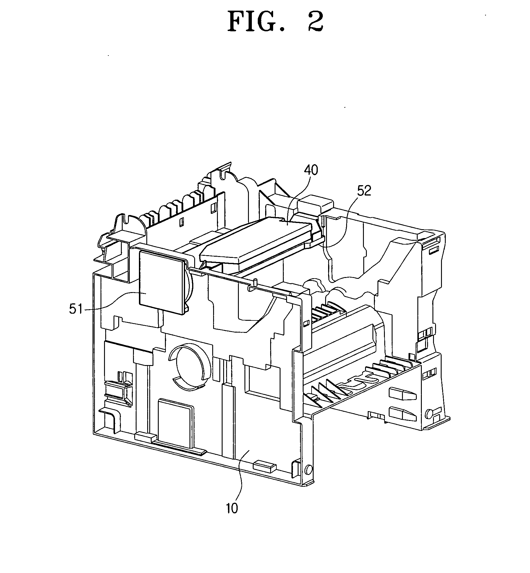
[0028]As shown in FIG. 1, the image forming apparatus according to an embodiment of the present invention comprises a housing 10, a image development part 20 installed inside the housing 10, which prints the image onto the print medium (i.e., paper, transparency, etc.), a fuser assembly 30, which fixes the image onto the print medium after the print medium has passed the image development part 20, by an application of high temperature and high pressure; a laser scanning unit 40, and a cooling unit 50.

[0029]A paper supply tray 11 is installed at a bottom of the housing 10. The print medium is picked up by the pick-up roller 12 from the paper supply tray...


PUM


Abstract

A cooling unit for use with an image forming apparatus including an image development part, with an Organic photoconductor, which is installed inside the housing and which forms an image, a laser scanning unit which scans the surface of the Organic photoconductor, and a fuser assembly which fixes the image transmitted from the image development part at a high temperature and a high pressure. The cooling unit cools the laser scanning unit and image development part, and includes a fan, which generates airflow at the time of operation, a support frame to support the laser scanning unit, and a guide member, disposed on the support frame, which guides the airflow towards the laser scanning unit and the image development part.

Description

CROSS-REFERENCE TO RELATED APPLICATION[0001]This application claims the benefit of Korean Patent Application No. 2006-11233, filed Feb. 6, 2006, in the Korean Intellectual Property Office, the disclosure of which is incorporated herein by reference.BACKGROUND OF THE INVENTION[0002]1. Field of the Invention[0003]Aspects of the present invention relate to a cooling device, which cools an image development cartridge and laser scanning unit used in forming images on print media, and an image forming apparatus having the same installed therein.[0004]2. Description of the Related Art[0005]Photocopiers, printers, multifunction apparatuses and similar image forming apparatuses may be broadly divided into color image forming apparatuses and black-and-white image forming apparatuses. The advantages of black-and-white image forming apparatuses compared to other image forming apparatuses are that they are generally smaller and provide faster printing speeds.[0006]Generally in black-and-white im...

Claims


Application Information

Patent Timeline
Patent Type & Authority Applications(United States)
IPC IPC(8): G03G21/20
CPCG03G15/04072G03G21/206G03G15/00G03G21/00
Inventor JEON, IN-CHEOL
Owner HEWLETT PACKARD DEV CO LP
Why Eureka
Try Eureka