Mechanism for can opener

a can opener and mechanism technology, applied in the field of mechanisms for can openers, can solve the problems of two separate kinds of actions, and it is difficult to fully automate a can opener of this type, and achieve the effect of widening the tolerance of grip and maximising the angle of cutting segments

Active Publication Date: 2007-08-02
DAKA RESEARCH INC
View PDF36 Cites 8 Cited by
  • Summary
  • Abstract
  • Description
  • Claims
  • Application Information

AI Technical Summary

Benefits of technology

[0028] Preferably, the intermittent drive means is additionally provided with control means to prevent intermittent rotation of the cutter wheel (either backwards or forwards, or preferably both) other than in response to the driving engagement of the drive peg with the intermittent drive teeth. The control means may additionally function to align the drive peg with the intermittent drive teeth to ensure smooth intermittent drive interaction.
[0031] Alternatively, the control means comprises a control surface (e.g. an upstanding broken circular wall) provided to the drive wheel and arranged to engage / disengage one or more (e.g. a pair of spaced) control pegs provided to the cutter wheel. The engage / disengage movement of the control surface with the one or more control pegs may for example, be arranged such that the control surface disengages the one or more control pegs just prior to engagement of the drive peg with the intermittently drivable element and engages the one or more control pegs subsequent thereto. Thus, again the cutter wheel never has any free movement, which could for example, otherwise lead to it either not cutting the can or to it becoming un-synchronised with the drive wheel. This type of control mechanism may be regarded as a ‘rotating wall Geneva’. An advantage of this approach is its simplicity.
[0034] The mechanism herein requires movement of the cutter wheel to a cutting position in which the cutter knife forms a nip, with its associated structures, with the drive wheel. It is desirable that the nip, with its associated structures, is as effective as possible.
[0035] Suitably, a spacer washer is therefore provided to the cutter wheel, which spacer washer shares the same second axis of rotation. The spacer washer is provided with a connector for connecting to the cutter wheel such that both may rotate together during the cutting action. The spacer washer is typically fashioned of resilient material e.g. rubber or a suitable synthetic polymer. Use of such a resilient material provides for a wider tolerance of grip. This in turn, enables the cutting segment angle to be maximised. It is this washer that, along with the drive, grips the rim of the can.
[0037] According to a further aspect of the present invention there is provided a can opener comprising the mechanism described above and drive means for driving the drive wheel thereof. The can opener typically comprises a housing shaped for receipt of the can and / or providing features facilitating user operability. Thus, for example, grip features may be provided to facilitate manual handling.
[0045] In a further aspect of the present invention, a locking eccentric mechanism provides a mechanical set and re-set based upon the use of a physical sensor which detects the presence of the not completely cut can. The locking bar is moved into a fixed socket which locks the cutter wheel to keep the blade in place during cutting. When the can lid is completely cut, the sensor is able to pushably displace the can with respect to the other mechanical components by a pushing action. This pushing action causes the locking bar to change to an unlocked position in which it not only frees itself from the fixed socket to free the cutter wheel, but also places the other end of the locking bar in a position to be pushed to re-start a toothed engagement with the cutter wheel by moving the teeth of the cutter wheel to a position in which the opposing teeth of the drive wheel can re-engage it and move it another half turn to cause the cutter wheel to disengage the now cut can lid.

Problems solved by technology

One problem with the can opener of GB 2 118 134 A1 and of its later variations is that two separate kinds of actions are required to achieve the cutting function.
The Applicant has appreciated that such requirement for these two separate kinds of actions makes it difficult to fully automate a can opener of this type.

Method used


Image

  • Mechanism for can opener
  • Mechanism for can opener
  • Mechanism for can opener

Examples


Embodiment Construction

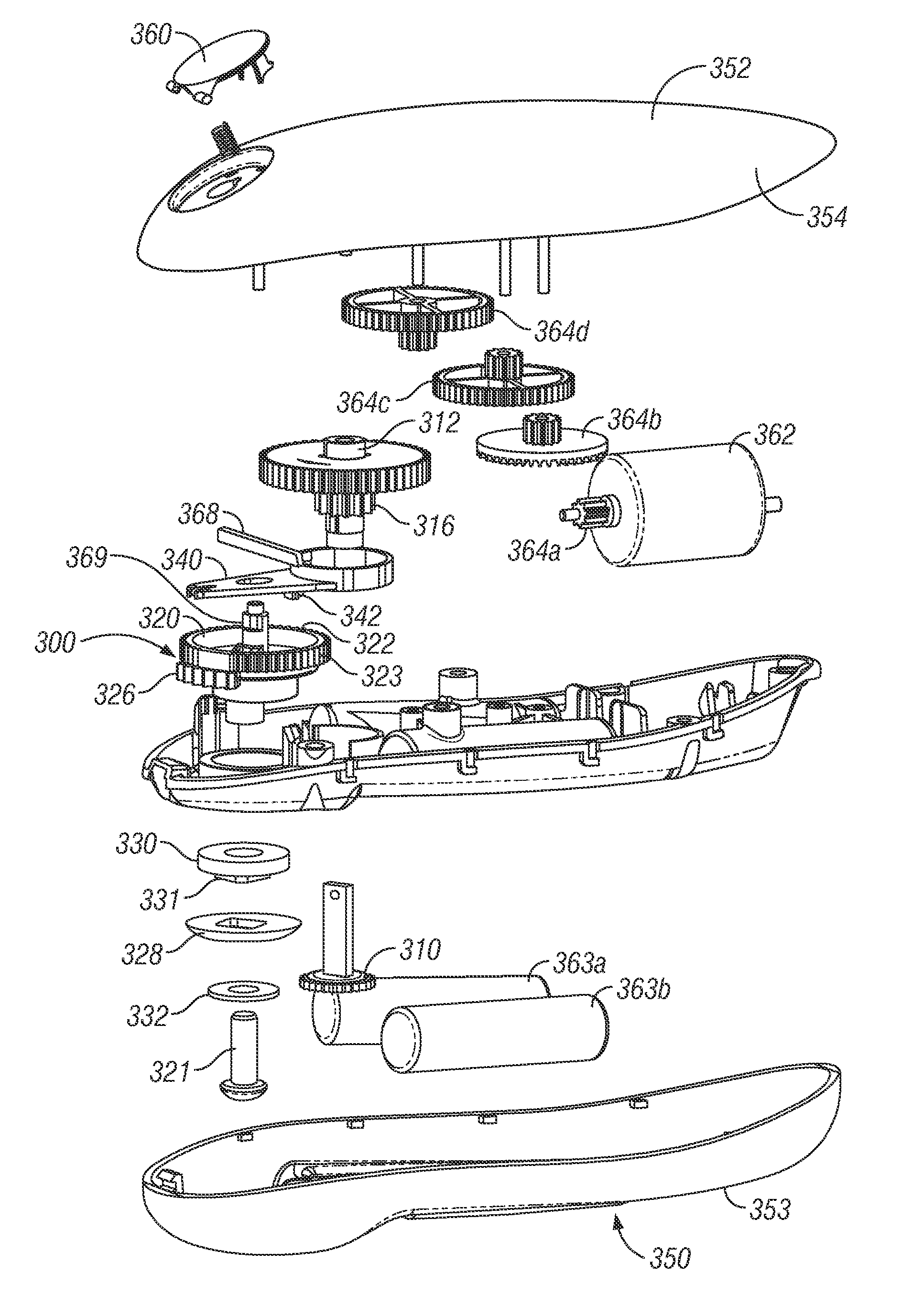
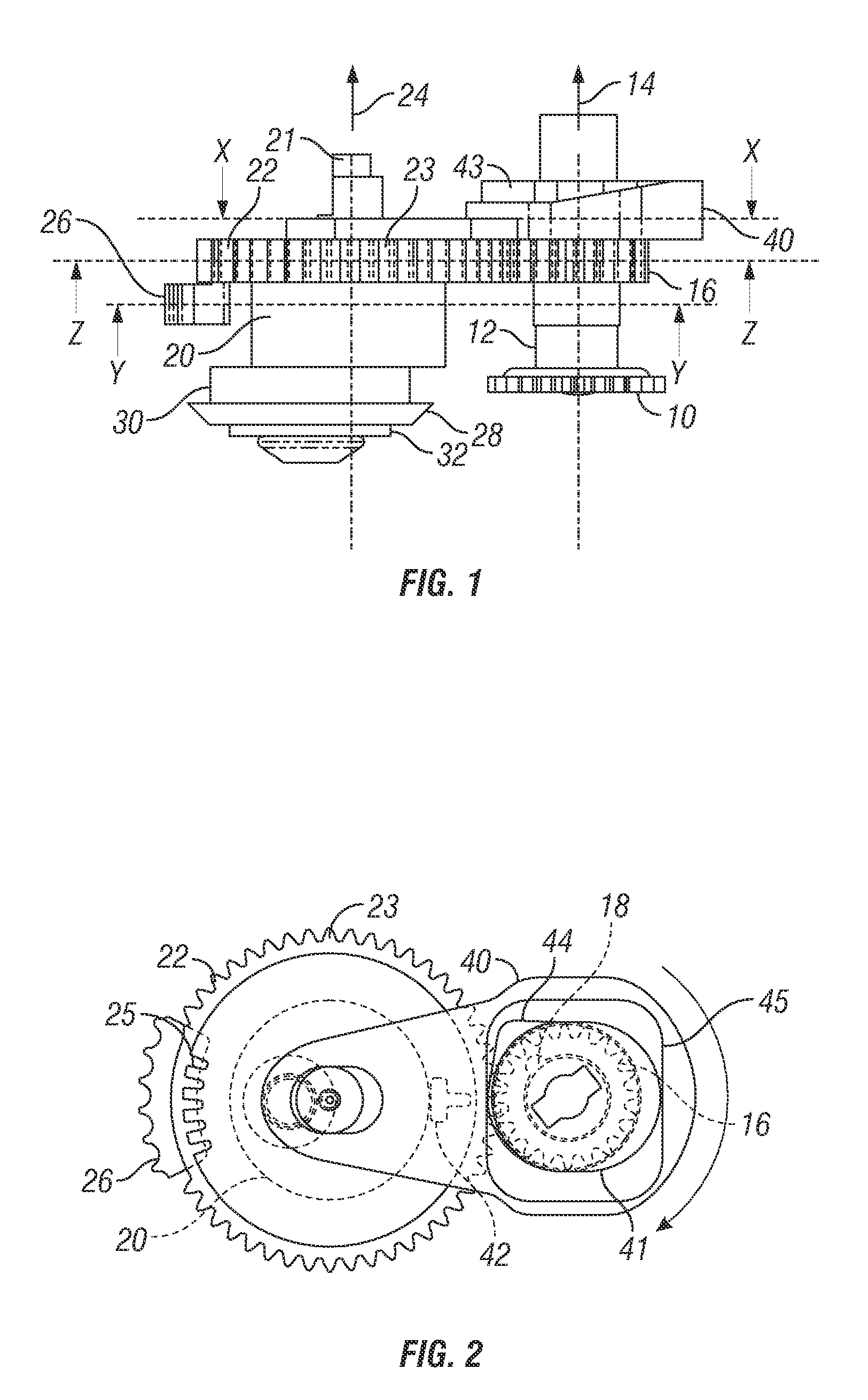
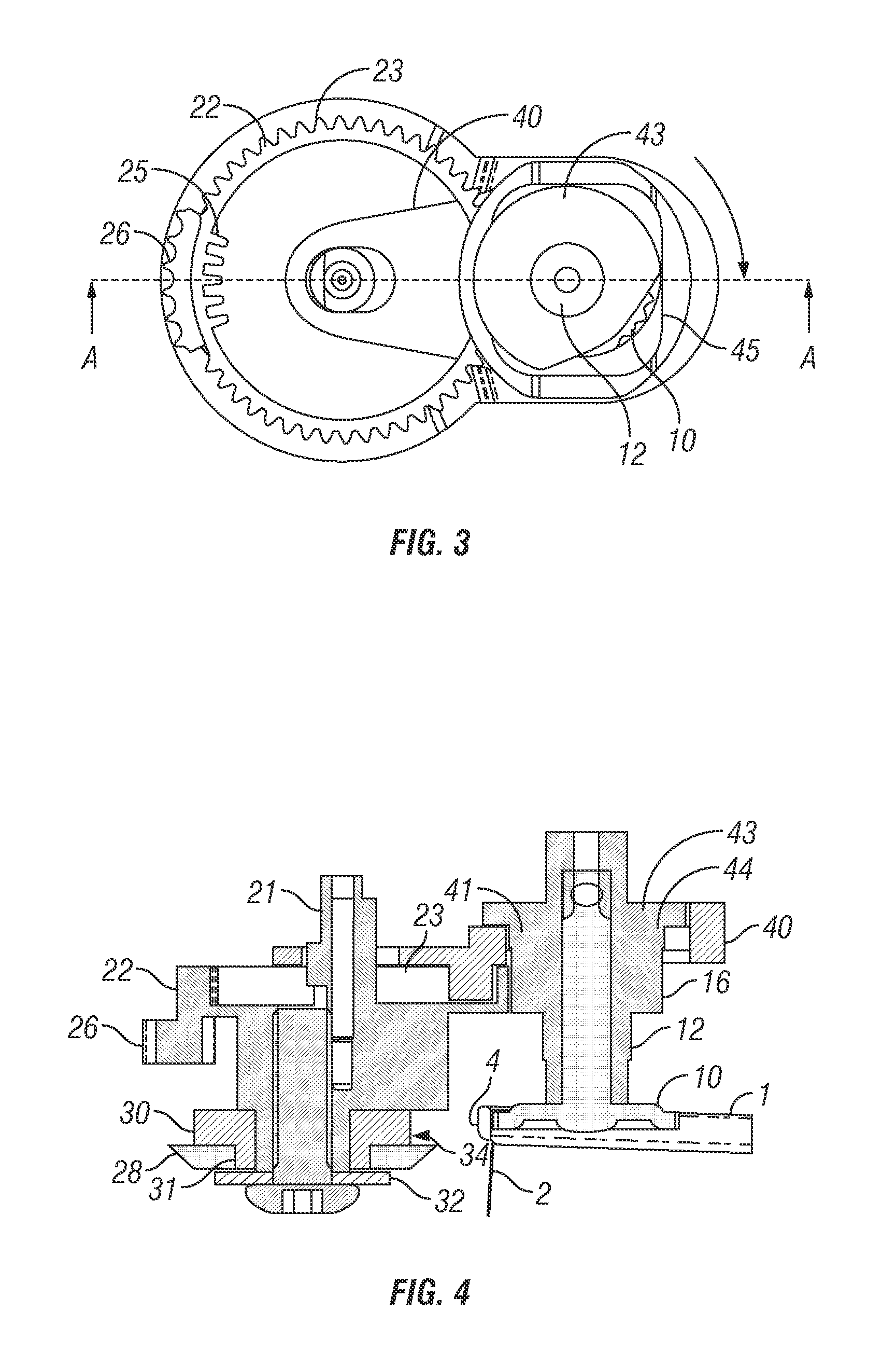
[0069] Referring now to the drawings, at FIGS. 1 to 4 there is shown a first can opener mechanism herein in the start (i.e. can disengaged) position. The mechanism comprises toothed drive wheel 10 mounted on drive spindle 12 arranged for rotation about drive axis 14. Also mounted on drive spindle 12 is drive gear 16, which is arranged to mesh with outer gear teeth 23 of the cutter drive gear 22 provided to cutter wheel 20 for drivable rotation thereof on cutter spindle 21 about cutter wheel axis 24. It may be seen at FIG. 2. that on the left hand side of the cutter drive gear 22 several outer gear teeth 23 are missing and replaced by inner gear teeth 25 and upstanding curved rack of teeth 26, the function of both of which will become clearer from the later description.

[0070] The cutter wheel 20 is further provided with a circular cutting knife 28, which eccentrically mounts thereto such that as the cutter wheel rotates about its axis 24 the cutting knife 28 is brought into close pr...


PUM


Abstract

There is provided a mechanism for use in a can opener comprising a body; rotationally mounting to said body about a first axis, a drive wheel for engaging the rim of the can; rotationally mounting to said body about a second axis and drivably rotatable by said drive wheel, a cutter wheel; eccentrically mounting to said cutter wheel, a cutting knife movable on rotation of the cutter wheel to a cutting position in which the cutter knife forms a nip with the drive wheel such that the cutting knife penetrates through the cylindrical wall of the can, and in which an electrical sensor can be used to reverse the position of the cutting wheel back to a start position and in which a mechanical sensor can be used in conjunction with a locking bar to advance the cutting wheel back to a start position.

Description

BACKGROUND OF THE INVENTION [0001] 1. Field of the Invention [0002] The present invention relates to a mechanism for use in a can opener that may be provided with a manual or automated drive means. [0003] Metal cans are a well-known form of packaging for preserved goods and generally comprise a cylindrical wall portion closed at both ends with a circular lid. The lid is usually fixed in place by providing an upstanding rim around the edge of the lid which is bent down in an inverted U-shape for clamping onto the end of the cylinder. [0004] 2. Related Background Art [0005] Two basic types of can opener are commonplace. The first type relies on making a circular cut around the lid near its edge typically within the upstanding rim. The second type relies on using a circular cutter knife to make a cut around the cylindrical wall portion of the can. Typically, the cut is made near the edge of the cylindrical part of the can but just below the lid so that when a complete circular cut is m...

Claims


Application Information

Patent Timeline
Patent Type & Authority Applications(United States)
IPC IPC(8): B67B7/46B67B7/90
CPCB67B7/34
Inventor MAH, PAT Y.SANDERS, MARK ANDREW
Owner DAKA RESEARCH INC
Why Eureka
Try Eureka