
Bone fixation and dynamization devices and methods

a bone fracture and dynamization technology, applied in the field of bone fracture stabilization and dynamization devices and methods, can solve the problems of increasing the risk of bone fracture, and increasing the risk of fractur

Inactive Publication Date: 2007-07-26
RICE UNIV
View PDF3 Cites 100 Cited by
  • Summary
  • Abstract
  • Description
  • Claims
  • Application Information

AI Technical Summary

Benefits of technology

[0014] Further disclosed herein is a method of dynamizing a fracture in a bone having a longitudinal axis comprising engaging a bone segment on each side of the fracture with at least one bone engagement pin; oscillating the bone

Problems solved by technology

For example, motor vehicle accidents, falls, direct impacts to joints or bones, the application of repetitive forces (e.g., such as may result from running) may cause various musculoskeletal injuries.
In general, a bone will likely fracture if more pressure or force is placed on the bone than the bone can stand.
Therefore, risks for a bone fracture increase as a bone weakens.
However, for patients who are unable or unwilling to load their bones through normal physical activities (e.g., bedridden, elderly, traumatized, or paraplegic patients), such conventional dynamization techniques may not be sufficient to achieve increased bone healing rates.
In addition, such conventional dynamization techniques may not be effective to enhance healing rates in fracture bones that bear minimal or no loads during the normal physical activities of the patient.
Further, in low gravity or microgravity environments, normal physical activities may not result in sufficient loading of the fractured bone segments necessary to enhance bone fracture healing.

Method used


Image

  • Bone fixation and dynamization devices and methods
  • Bone fixation and dynamization devices and methods
  • Bone fixation and dynamization devices and methods

Examples


Embodiment Construction

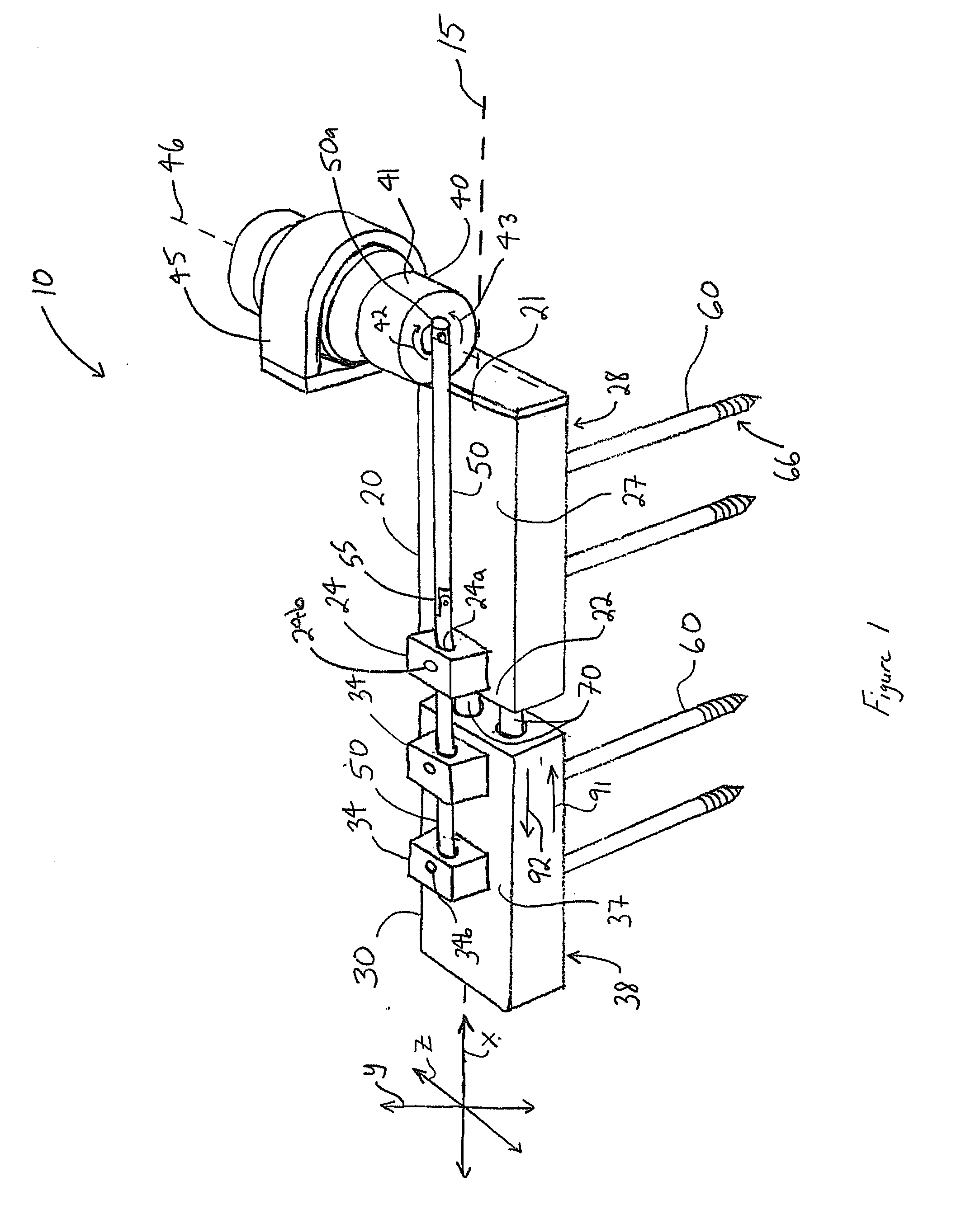
[0012] Disclosed herein is a bone fixation and dynamization device comprising a first member having a first end and a second end; a second member having a first end and a second end, wherein the first end of the second member is coupled to the second end of the first member body, wherein the first member is linearly moveable relative to the second member; an actuator coupled to the first member; a feedback controller coupled to the actuator; an elongate rod having an actuator end coupled to the actuator and a fixed end fixed to the second member, wherein the actuator is operable to move the rod and the second member linearly relative to the first member responsive to the feedback controller; at least one bone engagement pin extending from the first member; and at least one bone engagement pin extending from the second member.

[0013] Further disclosed herein is a method for fixing and dynamizing a fracture in a bone, comprising (b) providing a bone fixation and dynamization device, w...


PUM


Abstract

A bone fixation and dynamization device comprising a first member having a first end and a second end; a second member having a first end and a second end, wherein the first end of the second member is coupled to the second end of the first member body, wherein the first member is linearly moveable relative to the second member; an actuator coupled to the first member; a feedback controller coupled to the actuator; an elongate rod having an actuator end coupled to the actuator and a fixed end fixed to the second member, wherein the actuator is operable to move the rod and the second member linearly relative to the first member responsive to the feedback controller; at least one bone engagement pin extending from the first member; and at least one bone engagement pin extending from the second member.

Description

CROSS-REFERENCE TO RELATED APPLICATIONS [0001] This application claims benefit of U.S. provisional application Ser. No. 60 / 738,381 filed Nov. 18, 2005, and entitled “Bone Fixation Device,” which is hereby incorporated herein by reference in its entirety. This application also claims benefit of U.S. provisional application Ser. No. 60 / 744,306 filed Apr. 5, 2006, and entitled “Bone Fixation Device,” which is hereby incorporated herein by reference in its entirety.STATEMENT REGARDING FEDERALLY SPONSORED RESEARCH OR DEVELOPMENT [0002] Not applicable. BACKGROUND [0003] 1. Field of the Invention [0004] The invention relates generally to devices and methods to stabilize a bone fracture and promote healing of the fracture. More particularly, the present invention relates to devices and methods to promote healing of a bone fracture by actively inducing micromovement of the fractured bone segments at the bone fracture site. [0005] 2. Background of the Invention [0006] Over 25 million people i...

Claims


Application Information

Patent Timeline
IPC IPC(8): A61F2/30
CPCA61B2017/00022A61B17/66
Inventor CHAN, ELAINEYANG, PETERGORDON, ALEXVU, ERICCHANG, CYNTHIALIEBSCHNER, MICHAEL
Owner RICE UNIV
Learn More