Eureka AIR delivers breakthrough ideas for toughest innovation challenges, trusted by R&D personnel around the world.
Video mirror system suitable for use in a vehicle
What is Al technical title?
Al technical title is built by PatSnap Al team. It summarizes the technical point description of the patent document.
a technology for video mirrors and vehicles, applied in television systems, vehicle cleaning, instruments, etc., can solve the problems of limiting its commercial use and success, deteriorating the driver's ability to efficiently and safely use the interior rearview mirror assembly, etc., to achieve the effect of maximizing the rearward field of view and readily viewing the images displayed by the video screen
Inactive Publication Date: 2007-07-26
DONNELLY CORP
View PDF99 Cites 200 Cited by
Summary
Abstract
Description
Claims
Application Information
AI Technical Summary
This helps you quickly interpret patents by identifying the three key elements:
Problems solved by technology
Method used
Benefits of technology
[0004] One objective of this invention is to provide a video screen at an interior mirror assembly in a way that maximizes rearward field of view by the reflector element and that enables the driver to readily view images displayed by the video screen. A further objective is to achieve this while simultaneously providing a variable reflectivity for the reflector element. Another objective is to provide an interior mirror-mounted video screen for use with at least one of a rear back-up camera, a baby-minder camera, and a sidelane-viewing camera.
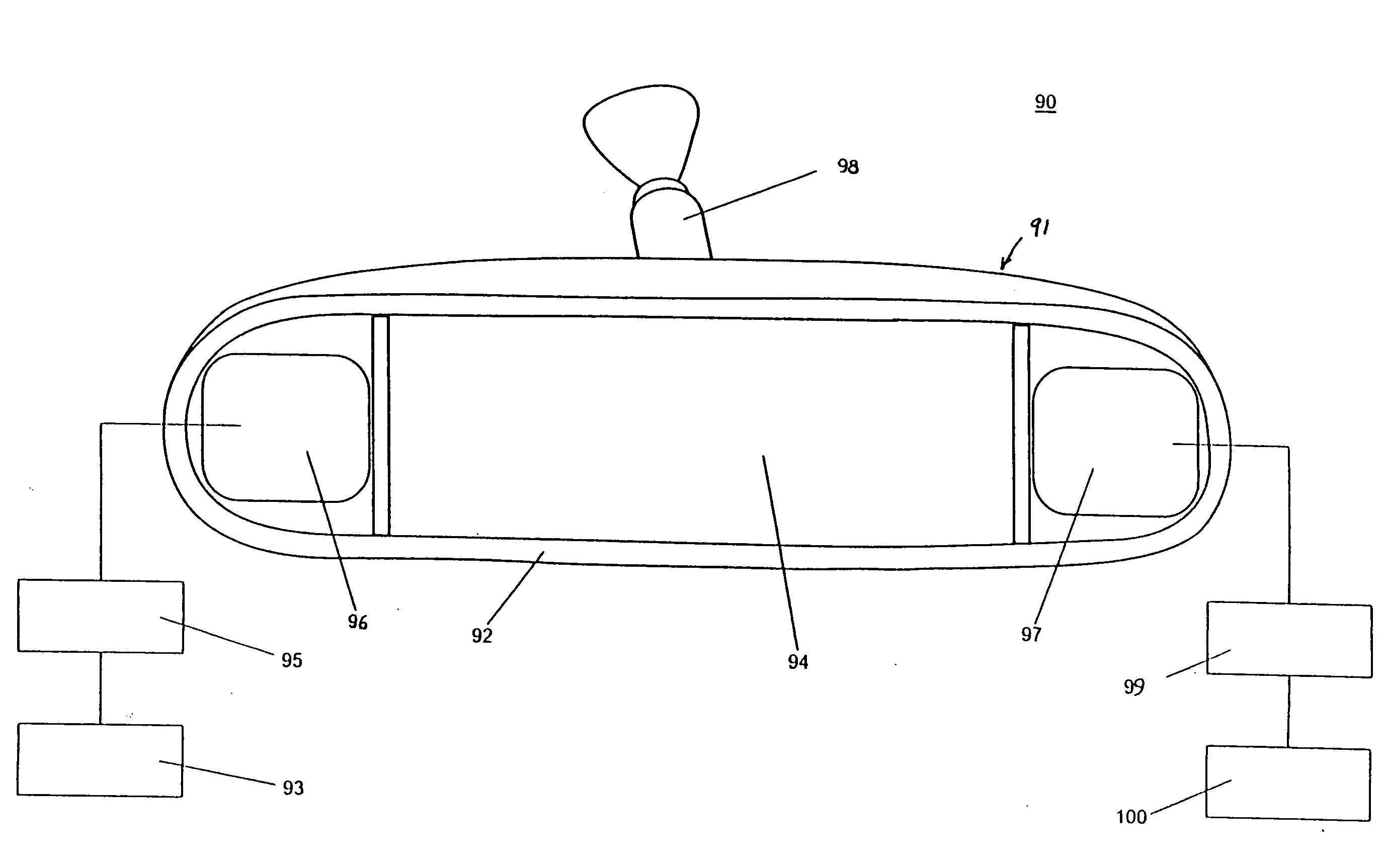
[0022] According to another form of the invention, a rear vision system for a vehicle includes an interior rearview mirror assembly and first and second image capturing devices. The interior rearview mirror assembly includes a mirror casing for mounting to the vehicle, which includes first and second video screens and a reflective element. The reflective element is positioned between the first and second video screens. The first image capturing device is positioned for viewing a driver side of the vehicle, with the second image capturing device positioned for viewing a passenger side of the vehicle. The first video screen is adapted for receiving the driver side image signals from the first image capturing device, while the second video screen is adapted to receive passenger side image signals from the second image capturing device. Together the first video screen, the reflective element, and the second video screen provide a cognitive and physical association between the images displayed on the first video screen, reflected images in the reflective element, and the images displayed on the second video screen to provide a rearward field of view of the vehicle when the mirror assembly is mounted to the vehicle.
[0038] In one aspect, the reflective element includes an anti-reflection coating over at least the opening to thereby reduce the glare and enhance the visibility of the video screen. For example, the anti-reflective element may comprise an anti-reflective film.
Problems solved by technology
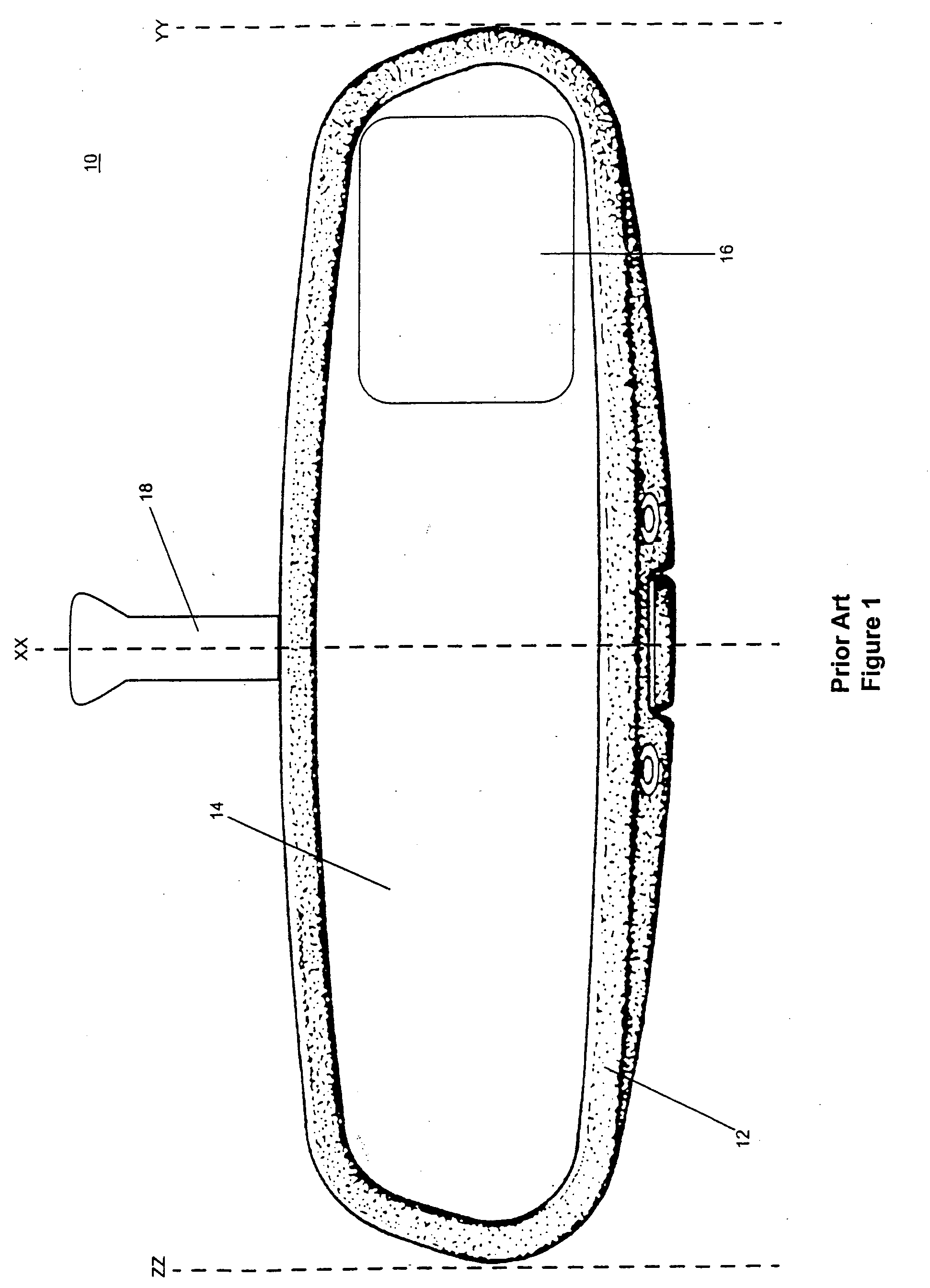
Although the known assembly as described in FIG. 1 can operate in certain circumstances, there are disadvantages that limit its commercial use and success.
Thus, the rearward field of view from reflector element 14 is significantly degraded, leading to deterioration in the driver's ability to efficiently and safely use interior rearview mirror assembly 10 to see rearward.
Method used
Image
Click on the blue label to locate the original text in one second.
Reading with bidirectional positioning of images and text.
Examples
Embodiment Construction
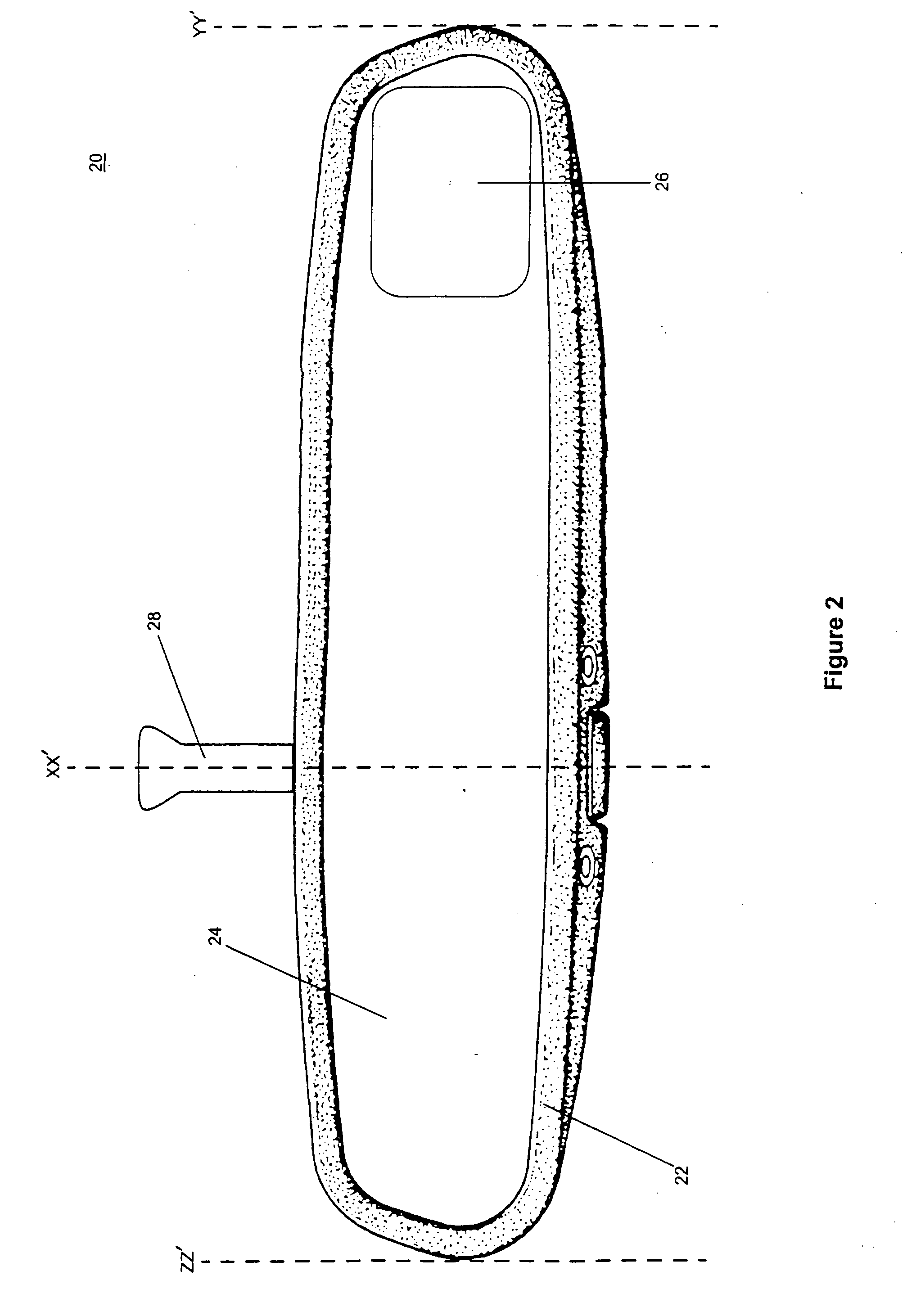
[0232] An improved interior rearview mirror assembly of the present invention is shown in FIG. 2. Interior rearview mirror assembly 20 is adapted for use in a left-hand drive vehicle. Thus, when interior rearview mirror assembly 20 is attached in or at an interior of a vehicle (such as to a windshield or to a header portion of the vehicle interior cabin, as known in the mirror arts), the driver of the vehicle is seated closer to portion ZZ′-XX′ (see FIG. 2) than to portion XX′-YY′. Video screen 26 is in portion XX′-YY′ of mirror casing 22 at a location as close as can be accommodated to the end of casing 22 farthest from the seating position of the driver in the vehicle. Casing 22 attaches to the vehicle via a mirror support arm 28 that projects from the rear (or alternately from the top) of casing 22 at a mounting portion located at a vertical cross-sectional line XX′. Thus, and importantly, the distance from ZZ′ to XX′ is less than the distance from XX′ to YY′ and the point of att...
PUM
Abstract
A vehicular video mirror system comprises an interior electrochromic mirror having a transflective mirror reflector and a video screen disposed behind the mirror reflector so that its presence is substantially unobservable to a driver of the vehicle until the video screen is actuated to emit light that passes through the electrochromic reflective element to be viewed by the driver of the vehicle. Common control circuit circuitry may control dimming of the electrochromic medium and actuation of the video screen. The control circuitry may receive a signal indicative of selection of a reverse gear of the vehicle by the driver and actuates the video screen in order to display video images captured by a video imaging device disposed to the rear of the vehicle and having a field of view rearward of and external to the vehicle.
Description
CROSS REFERENCE TO RELATED APPLICATIONS [0001] This application is a continuation of pending U.S. patent application Ser. No. 10 / 755,915, filed Jan. 13, 2004 entitled VIDEO MIRROR SYSTEMS INCORPORATING AN ACCESSORY MODULE (Attorney Docket DON01 P-1133), which is a continuation of U.S. application Ser. No. 09 / 793,002, filed Feb. 26, 2001, now U.S. Pat. No. 6,690,268 (DON01 P-869), which claims benefit of and incorporates by reference herein in their entireties U.S. provisional applications, Ser. No. 60 / 263,680, filed Jan. 23, 2001 (DON01 P-876); Ser. No. 60 / 243,986, filed Oct. 27, 2000 (DON01 P-857); Ser. No. 60 / 238,483, filed Oct. 6, 2000 (DON01 P-849); Ser. No. 60 / 237,077, filed Sep. 30, 2000 (DON01 P-846); Ser. No. 60 / 234,412, filed Sep. 21, 2000 (DON01 P-841); Ser. No. 60 / 218,336, filed Jul. 14, 2000 (DON01 P-831); and Ser. No. 60 / 186,520, filed Mar. 2, 2000 (DON01 P-802). BACKGROUND OF THE INVENTION [0002] Practically every passenger-carrying vehicle (such as sedans, convertible...
Claims
Application Information
Patent Timeline
Application Date:The date an application was filed.
Publication Date:The date a patent or application was officially published.
First Publication Date:The earliest publication date of a patent with the same application number.
Issue Date:Publication date of the patent grant document.
PCT Entry Date:The Entry date of PCT National Phase.
Estimated Expiry Date:The statutory expiry date of a patent right according to the Patent Law, and it is the longest term of protection that the patent right can achieve without the termination of the patent right due to other reasons(Term extension factor has been taken into account ).
Invalid Date:Actual expiry date is based on effective date or publication date of legal transaction data of invalid patent.
Patent Type & Authority Applications(United States)