
Three-way direct pilot valve

a pilot valve and three-way technology, applied in the direction of multiple-way valves, valve details, valve arrangements, etc., can solve the problems of cylinders or main valves coupled to pilot valves that are difficult to control, cylinders or main valves that are coupled to pilot valves that are also difficult to provide reliable pilot valves, etc., to achieve compact and simplified design, the effect of increasing the overall for

Inactive Publication Date: 2007-07-19
ASCO CONTROLS LP
View PDF5 Cites 42 Cited by
  • Summary
  • Abstract
  • Description
  • Claims
  • Application Information

AI Technical Summary

Benefits of technology

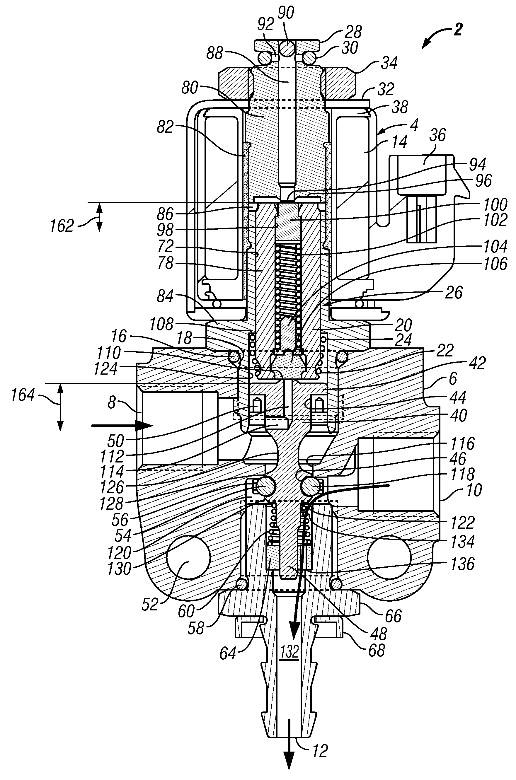
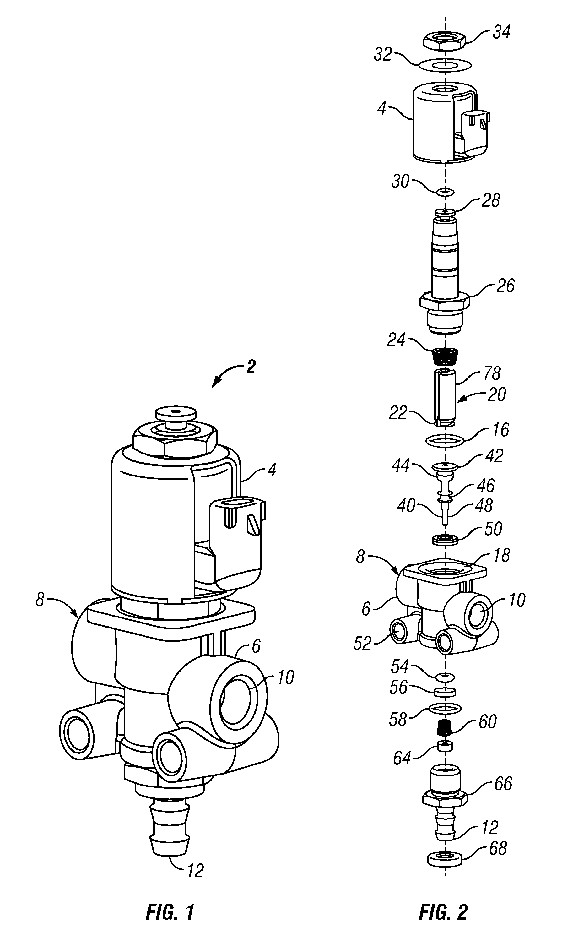
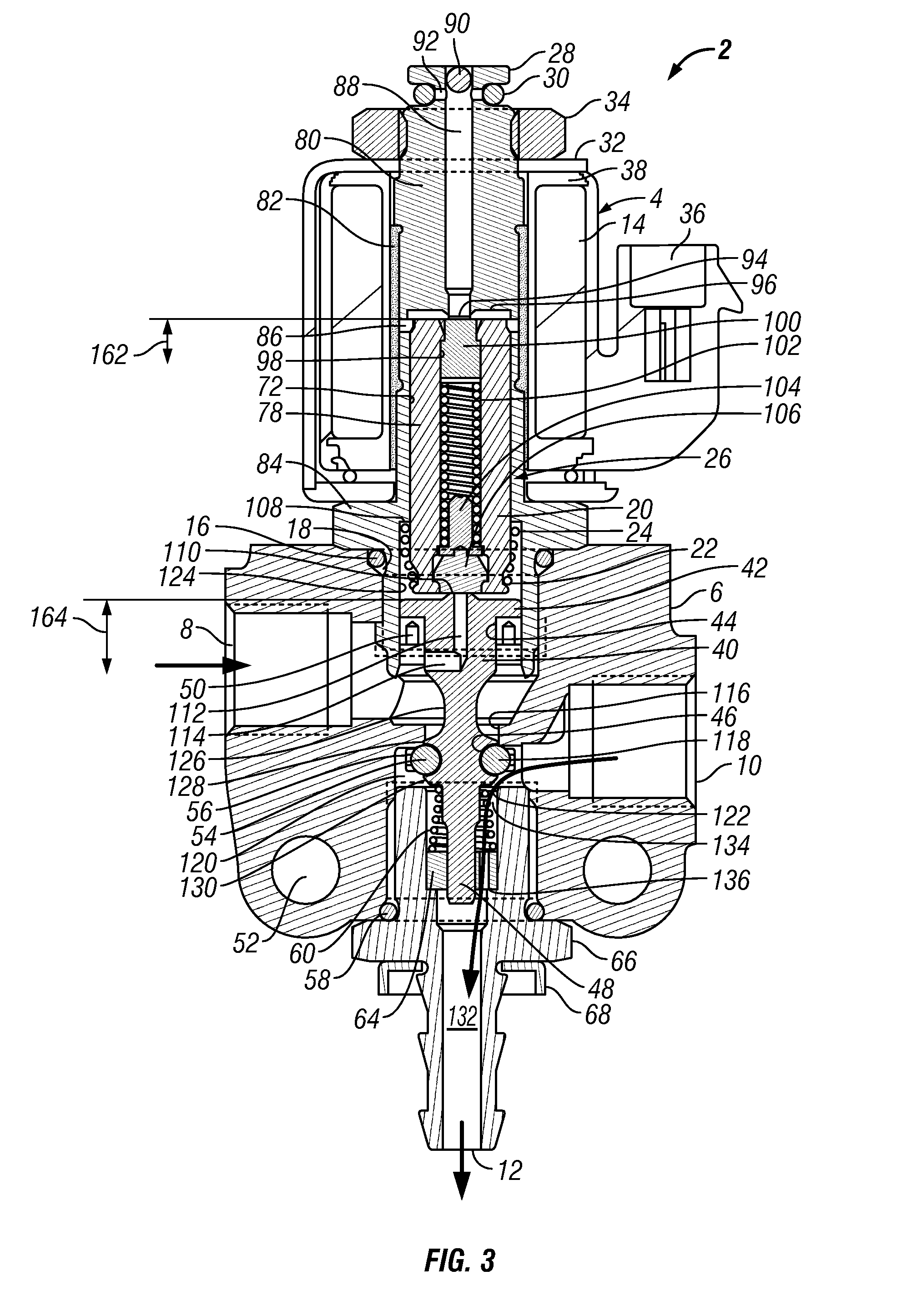
[0013]The present disclosure provides a method, apparatus, and system of an inline direct acting solenoid pilot valve. The valve has a solenoid assembly with a longitudinally moveable core assembly that shifts alternatively between sealing engagement on a lower first end of the core assembly with a pilot port formed in a poppet and sealing engagement on an opposite upper end with a stationary pilot exhaust port in the solenoid assembly. The core assembly can move in the same or opposite direction than the poppet and thus is independently moveable from the poppet to effect the various modes of operation. Because the movement is independent, the core assembly can advantageously operate within the solenoid with a shorter stroke to produce a higher overall force per length relative to a conventional core assembly stroke that is longer than the poppet stroke. The overall design allows a more compact and simplified and therefore believed to be more reliable design for a pilot valve that still achieves the purposes intended for a three way pilot valve. The pilot port and the pi

Problems solved by technology

Without the pilot valve, the cylinder may be difficult to control or the main valve might require a larger than available power source to operate and function as intended.
Since the electrical solenoid can only move the armature in an up-and-down motion, often complex linkages and flow paths are needed to allow the pilot valve to function in a desired manner to provide the various flow paths.
Further, if power is lost to the solenoid or from an inlet pressure, the pilot valve may fail in an uncontrolled position, in turn causing the cylinder or the main valve coupled to the pilot valve to also fail.
More linkages, more seals, and more cumulative effects of combined manufacturing tolerances can create difficulty in providing a reliable pilot valve.
Yet, the complexity is often necessary to accomplish the needed flow path interconnections.
Such pilot valves may be relatively simple in design but are not able to accomplish some desired operations, due to their simplicity, such as being generally limited in their flow areas at a given pressure due to the power required to actuate a sufficiently large solenoid.
The force generated by a solenoid decreases sharply as the armature extends in its stroke, and causes design complications to provide adequate force throughout the armature stroke for the valve to operate properly.

Method used


Image

  • Three-way direct pilot valve
  • Three-way direct pilot valve
  • Three-way direct pilot valve

Examples


Embodiment Construction

[0034]One or more illustrative embodiments incorporating the invention disclosed herein are presented below. Not all features of an actual implementation are described or shown in this application for the sake of clarity. It is understood that the development of an actual embodiment incorporating the present invention, numerous implementation-specific decisions must be made to achieve the developer's goals, such as compliance with system-related, business-related and other constraints, which vary by implementation and from time to time. While a developer's efforts might be complex and time-consuming, such efforts would be, nevertheless, a routine undertaking for those of ordinary skill in the art having benefit of this disclosure.

[0035]FIG. 1 is a perspective schematic view of an exemplary pilot valve according to the teachings in this disclosure. The pilot valve 2 includes generally a solenoid assembly 4 coupled to a body 6. The body 6 in at least one embodiment includes an inlet p...


PUM


Abstract

The present disclosure provides a method, apparatus, and system of an inline direct acting solenoid pilot valve. The valve has a solenoid assembly with a longitudinally moveable core assembly that shifts alternatively between sealing engagement on a lower first end of the core assembly with a pilot port formed in a poppet and sealing engagement on an opposite upper end with a stationary pilot exhaust port in the solenoid assembly. The core assembly can move in the same or opposite direction than the poppet and thus is independently moveable from the poppet to effect the various modes of operation. Because the movement is independent, the core assembly can advantageously operate within the solenoid with a shorter stroke to produce a higher overall force per length relative to a conventional core assembly stroke that is longer than the poppet stroke. The overall design allows a more compact and simplified design.

Description

CROSS REFERENCE TO RELATED APPLICATIONS[0001]This application claims the benefit of U.S. Provisional Application No. 60 / 758,848, filed Jan. 13, 2006, and is incorporated herein by reference.STATEMENT REGARDING FEDERALLY SPONSORED RESEARCH OR DEVELOPMENT[0002]Not applicable.NAMES OF PARTIES TO A JOINT RESEARCH AGREEMENT[0003]Not applicable.REFERENCE TO APPENDIX[0004]Not applicable.BACKGROUND[0005]1. Field of the Invention[0006]The invention relates to control valves. More specifically, the invention relates to pilot valves for the control of a device.[0007]2. Description of Related Art[0008]Control valves are widely used in industry generally to control the flow of fluid through interconnected flow paths. A pilot valve is a particular category of control valve that can operate on relatively small fluidic flow rates or small amounts of electrical power from a control system. Often a pilot valve is used in conjunction with a fluidic cylinder to actuate other devices or with a larger ma...

Claims


Application Information

Patent Timeline
IPC IPC(8): F16K31/12
CPCF16K11/044F16K31/423F16K31/0603
Inventor VOLZ, GREGORY
Owner ASCO CONTROLS LP
Learn More