
Cerenkov x-ray detector for portal imaging

a detector and portal imaging technology, applied in radiation measurement, instruments, photoelectric discharge tubes, etc., can solve the problems of low x-ray absorption or low quantum efficiency

Inactive Publication Date: 2007-07-19
SUNNYBROOK HEALTH SCI CENT
View PDF6 Cites 18 Cited by
  • Summary
  • Abstract
  • Description
  • Claims
  • Application Information

AI Technical Summary

Benefits of technology

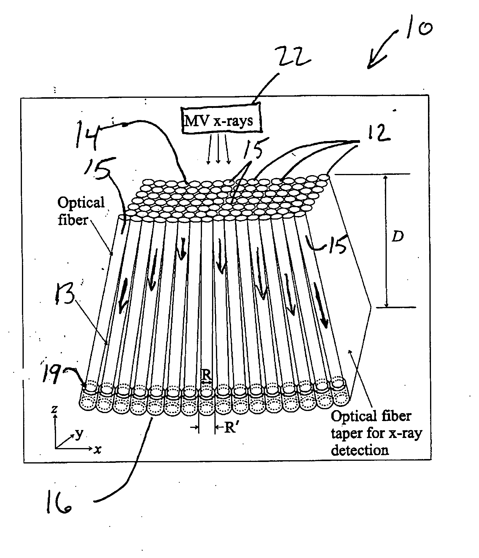
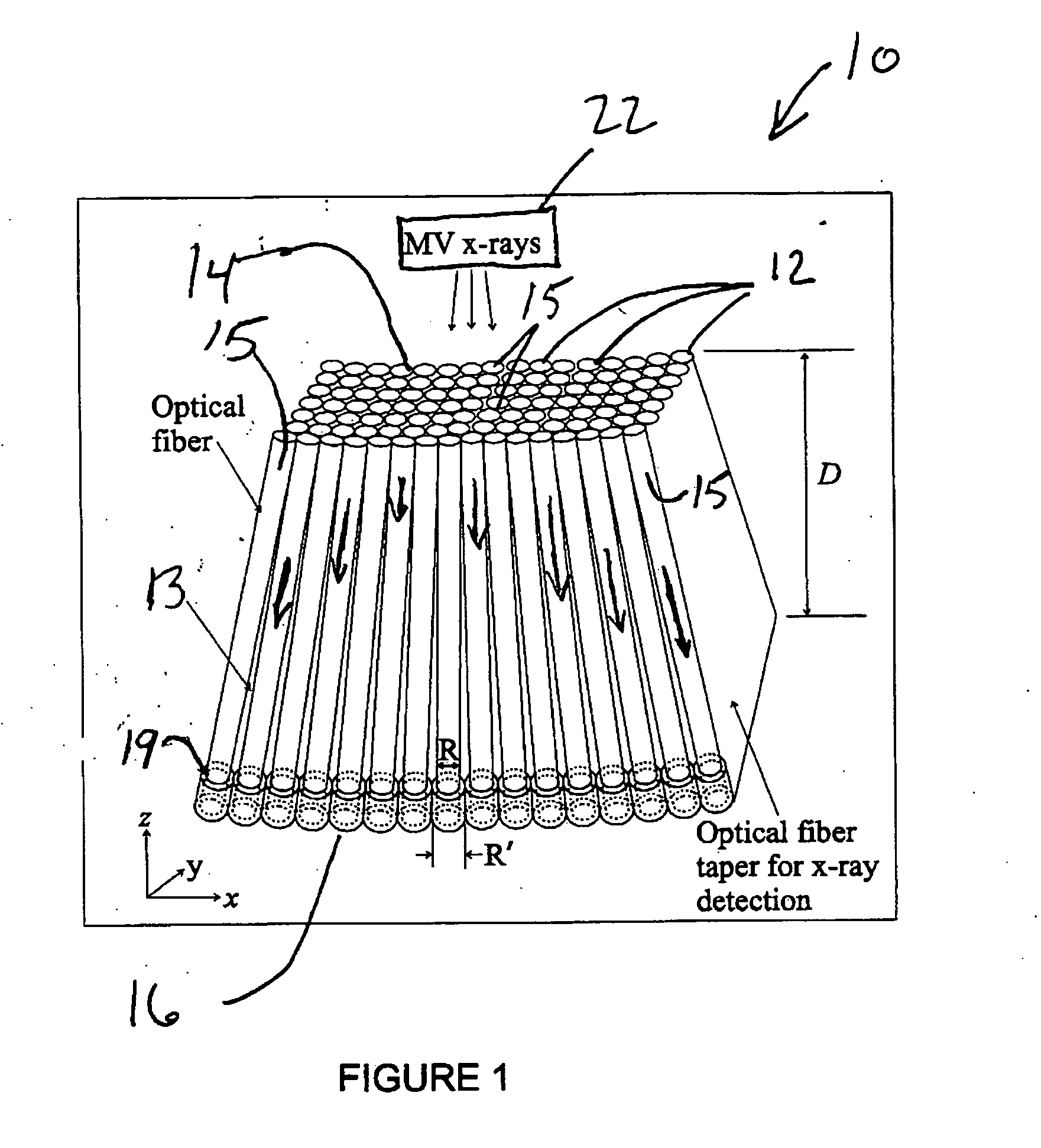
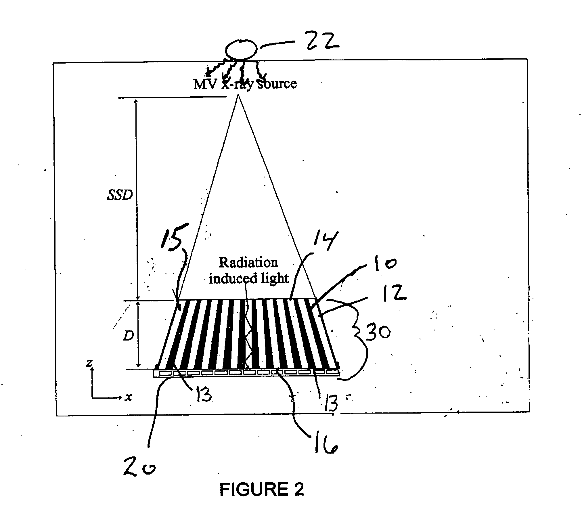
[0006] The present invention provides an x-ray detector that uses Cerenkov radiation to convert x-ray energies into light for portal imaging applications. The x-ray detector disclosed herein has a QE that can be more than 80% and yet has a spatial resolution equivalent to that of current EPIDs. The detective quantum efficiency (DQE) at the zero frequency can also be as high as 40%, which is over 20 times higher than that of current EPIDs. In addition, the optical light guides forming the detector of the present invention are made of low-atomic number materials, a potential advantage for transit dosimetry in radiation therapy.

Problems solved by technology

The main problem with this approach is that the Cu plate / phosphor screen must be thin (˜2 mm thick) in order to obtain a high spatial resolution, resulting in a low x-ray absorption or low quantum efficiency (QE), which is typically on the order of 2-4% as compared to the theoretical limit of 100%.

Method used


Image

  • Cerenkov x-ray detector for portal imaging
  • Cerenkov x-ray detector for portal imaging
  • Cerenkov x-ray detector for portal imaging

Examples


Embodiment Construction

[0014] Generally speaking, the systems described herein are directed to a detector for portal imaging. As required, embodiments of the present invention are disclosed herein. However, the disclosed embodiments are merely exemplary, and it should be understood that the invention may be embodied in many various and alternative forms. The Figures are not to scale and some features may be exaggerated or minimized to show details of particular elements while related elements may have been eliminated to prevent obscuring novel aspects. Therefore, specific structural and functional details disclosed herein are not to be interpreted as limiting but merely as a basis for the claims and as a representative basis for teaching one skilled in the art to variously employ the present invention. For purposes of teaching and not limitation, the illustrated embodiments are directed to a detector for portal imaging.

[0015] As used herein, the term “about”, when used in conjunction with ranges of dimen...


PUM


Abstract

The present invention provides a practical design of a megavoltage x-ray detector with both high quantum efficiency (QE) and high resolution. The x-ray detector includes an optical-fiber taper (OFT) made from a large number of optical fibers, each of which is aligned with the incident x-rays from an x-ray source hitting a top surface of the optical fiber taper. The optical-fiber taper is a matrix of optical fibers with the core material made of, e.g., silica and coated with a cladding glass or polymer such that light created within the core of each optical fiber will be guided to the bottom ends of the fiber with the ends of the fibers at the bottom being optically coupled to and optical image read-out device. Each optical fiber in the optical fiber taper is fully aligned with the incident x-ray source so that x-rays entering the top of the fiber travel directly towards the bottom of the same fiber. This alignment (or focusing) of the optical-fiber taper towards the x-ray source can be achieved by an extra coating at the bottoms of the optical fibers so they have a larger diameter than the other top ends of the fibers.

Description

CROSS REFERENCE TO RELATED U.S PATENT APPLICATION. [0001] This patent application relates to U.S. provisional patent application Ser. No. 601759,571 filed on Jan. 18, 2006 entitled CERENKOV X-RAY DETECTOR FOR PORTAL IMAGING, filed in English, which is incorporated herein in its entirety by reference.FIELD OF THE INVENTION [0002] The present invention relates generally to improved electronic portal imaging devices (EPIDs) used in radiation therapy, and more particularly the present invention relates to a high quantum efficiency (QE) x-ray detector based on Cerenkov radiation (or Cerenkov light) for portal imaging application. BACKGROUND OF THE INVENTION [0003] Electronic portal imaging devices (EPIDs) are important tools for treatment verification in Radiation Therapy. Most EPIDs developed so far for portal imaging application [using megavoltage (MV) x-rays] use a Cu plate / phosphor screen to absorb x-rays and convert their energies into light, and the light image is then read out by ...

Claims


Application Information

Patent Timeline
IPC IPC(8): G01T1/20
CPCG01T1/22G01T1/29
Inventor PANG, GEORDI G.ROWLANDS, JOHN A.
Owner SUNNYBROOK HEALTH SCI CENT
Learn More