Valve timing controller
- Summary
- Abstract
- Description
- Claims
- Application Information
AI Technical Summary
Benefits of technology
Problems solved by technology
Method used
Image
Examples
first embodiment
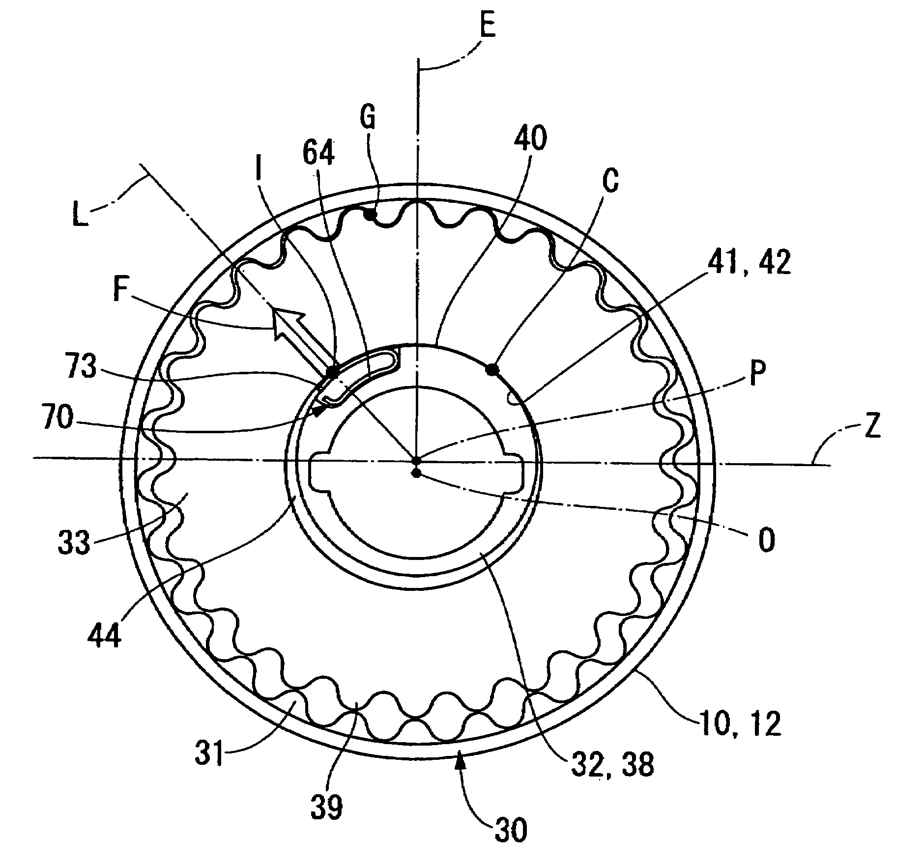
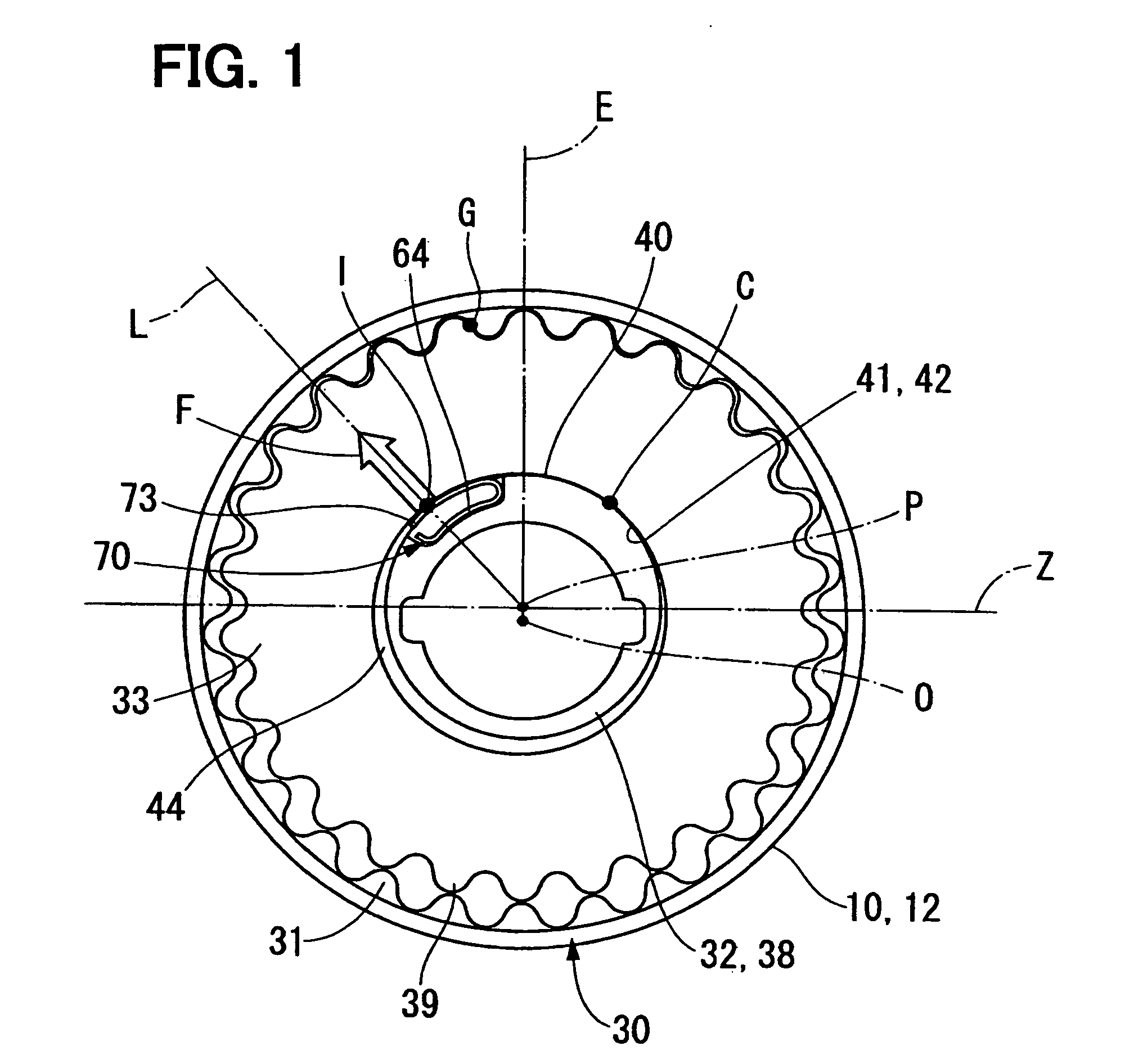
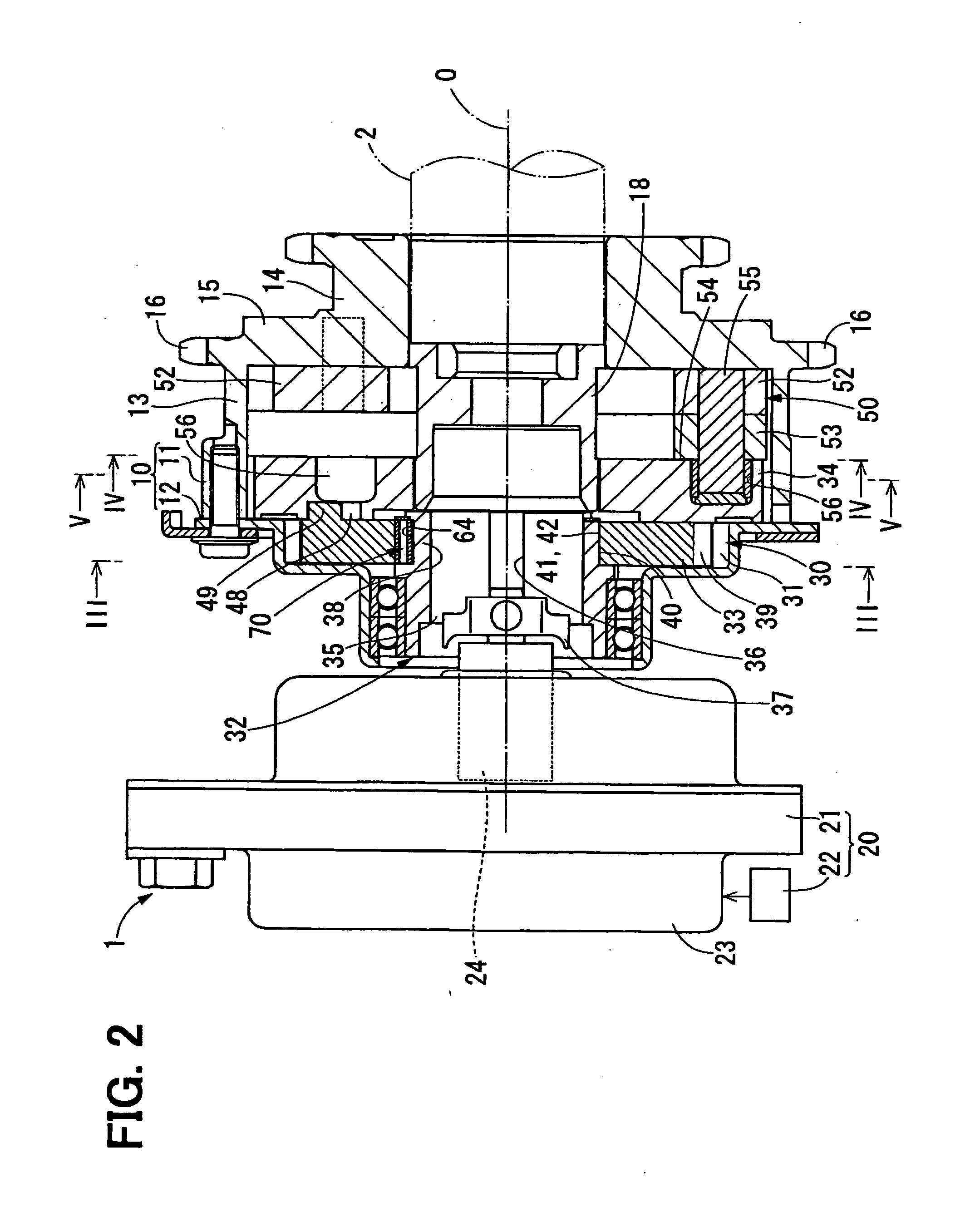
[0044]FIG. 2 shows a valve timing controller 1 in a first embodiment of the present invention. The valve timing controller 1 is provided in a transmission system for transmitting an engine torque from a crankshaft to a camshaft 2 for an internal combustion engine. The valve timing controller 1 changes a relative rotational phase of the camshaft to the crankshaft (hereinafter referred to as “engine shaft phase”) to adjust valve timing of an intake valve for the engine.
[0045]The valve timing controller 1 is provided with a drive-side rotational element 10, a driven-side rotational element 18, a control unit 20, a differential gear mechanism 30 and a link mechanism 50.
[0046]The drive-side rotational element 10 is formed in a hollow shape as a whole and receives the differential gear mechanism 30, the link mechanism 50 and the like therein. The drive-side rotational element 10 includes a two-shoulder cylindrical sprocket 11 and a two-shoulder cylindrical cover gear 12, a large diameter-...
second embodiment
[0076]As shown in FIGS. 9 and 10, a second embodiment of the present invention is a modification of the first embodiment.
[0077]In a differential gear mechanism 110 of a valve timing controller 100 in the second embodiment, a planetary bearing 120 is added between the gear inner peripheral surface 42 of the planetary gear 33 and the eccentric outer peripheral surface 40 of the eccentric cam portion 38. The planetary bearing 120 is a radial bearing holding ball-shaped rolling elements 123 between an outer ring 121 and an inner ring 122. An outer periphery 126 of the outer ring 121 is press-fitted into the gear inner peripheral surface 42 to rotate integrally with the planetary gear 33 and on the other hand, an inner peripheral surface 125 of a central bore 124 of the inner ring 122 is slidably and rotatably engaged with the eccentric outer peripheral surface 40. A clearance due to a manufacturing tolerance or the like is formed in the engagement boundary face between the inner periphe...
third embodiment
[0080]As shown in FIGS. 11A and 11B, a third embodiment of the present invention is a modification of the first embodiment.
[0081]In a differential gear mechanism 160 of a valve timing controller 150 in the third embodiment, a washer member 170 is added as a part of the planetary carrier 32 between the receiving portion 64 of the eccentric cam portion 38 and the spring member 70. The washer member 170 is made of a metallic sheet or the like and mostly has a circular cross section bent along the inner-peripheral-side contact portion 72 of the spring member 70 and the inner bottom face 66 of the receiving portion 64. A curvature radius Re, Rf of each of an inner peripheral surface 171 and an outer peripheral surface 172 of the washer member 170 is set to be smaller than a curvature radius Rb of the inner bottom surface 66 of the receiving portion 64 and larger than a curvature radius Ra of the inner-peripheral-side contact portion 72. Thereby, the inner peripheral surface 171 of the wa...
PUM
 Abstract
Description
Claims
Application Information
 - R&D
- Intellectual Property
- Life Sciences
- Materials
- Tech Scout
- Unparalleled Data Quality
- Higher Quality Content
- 60% Fewer Hallucinations
Browse by: Latest US Patents, China's latest patents, Technical Efficacy Thesaurus, Application Domain, Technology Topic, Popular Technical Reports.
© 2025 PatSnap. All rights reserved.Legal|Privacy policy|Modern Slavery Act Transparency Statement|Sitemap|About US| Contact US: help@patsnap.com


