Locking mechanism for restraints with improved resilience

a technology of locking mechanism and restraint, which is applied in the field of locking mechanism for restraints, can solve the problems of reducing the reliability of the device, affecting the safety of the device, and the design may not only be picked too easily, so as to reduce the possibility of inadvertent unlocking and increase the difficulty of picking the lock

Inactive Publication Date: 2007-07-19
UNIVERSAL TOOL
View PDF16 Cites 10 Cited by
  • Summary
  • Abstract
  • Description
  • Claims
  • Application Information

AI Technical Summary

Benefits of technology

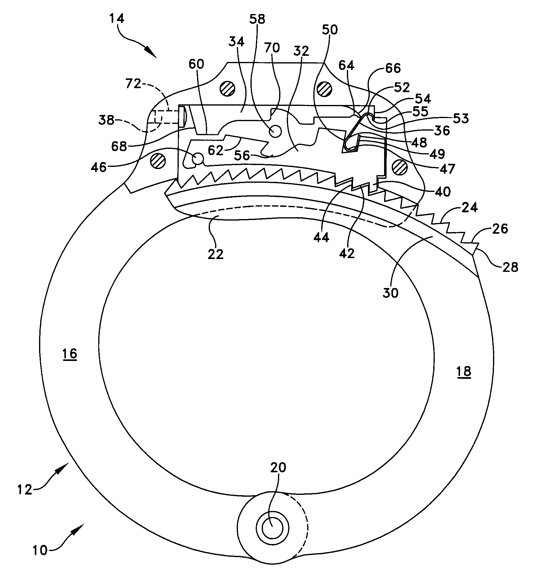
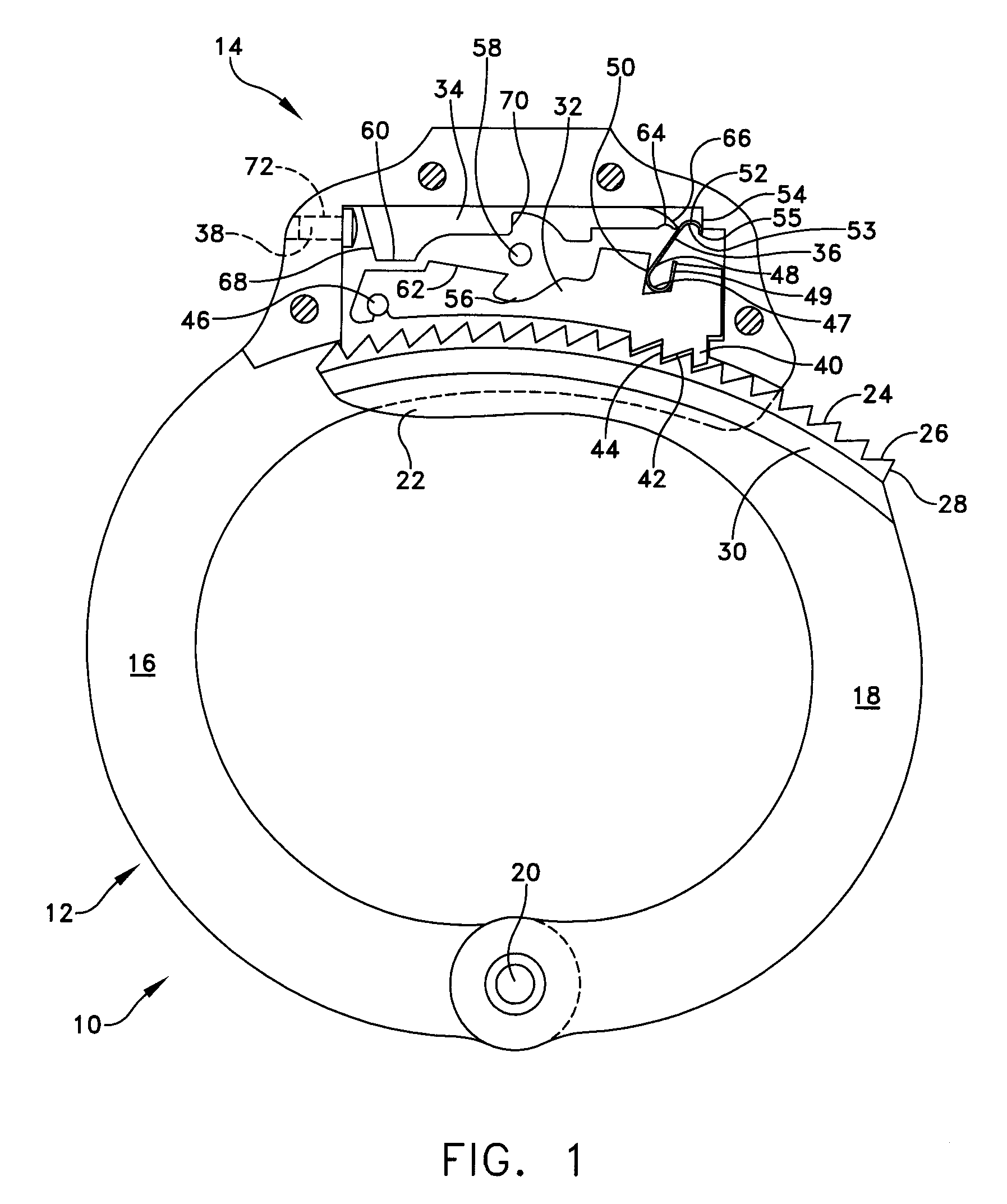
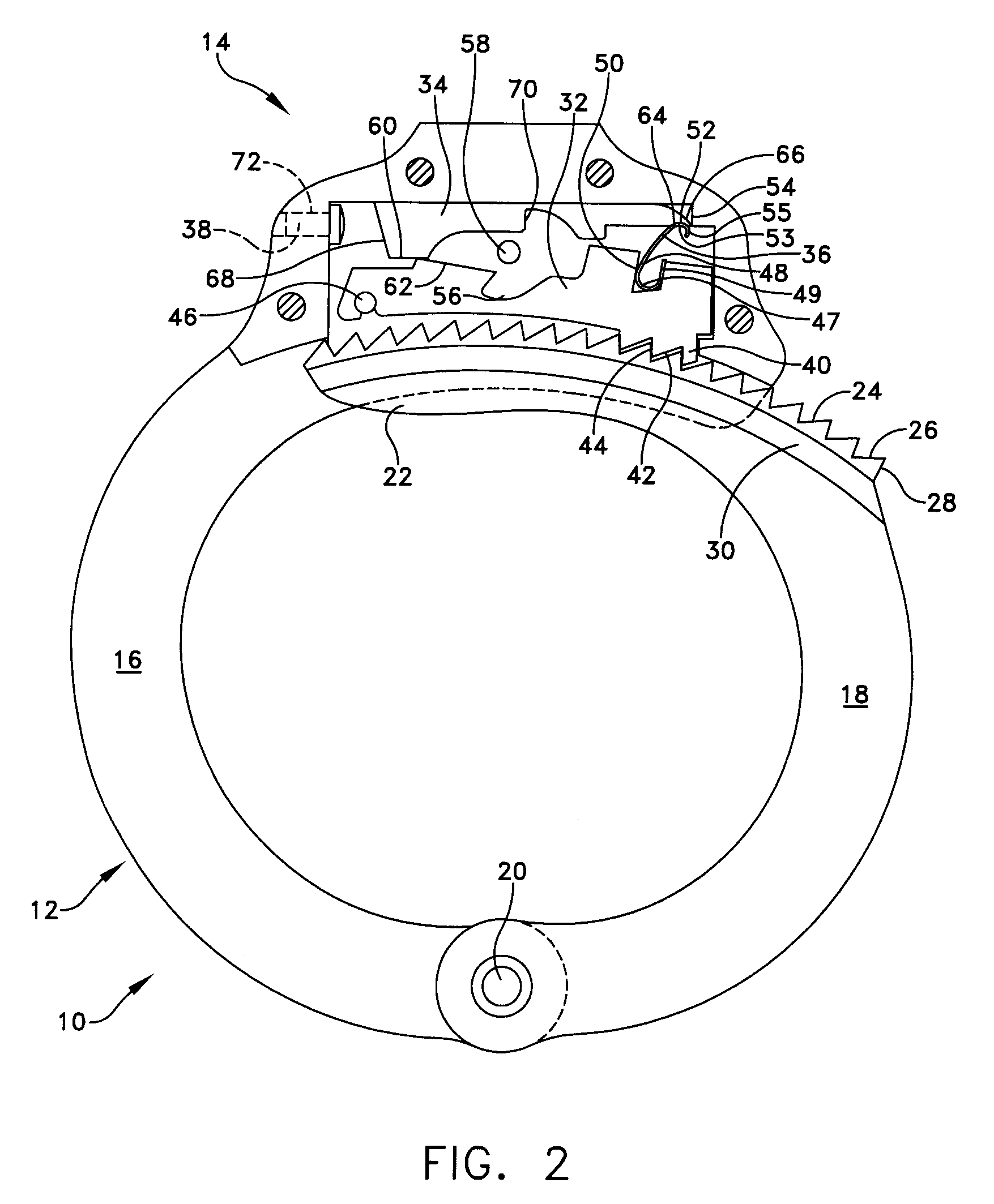
[0023]The present invention provides an improved locking mechanism for restraints, providing a decreased possibility of inadvertent unlocking of the double lock mechanism, and increased difficulty in picking the lock. The improved locking mechanism will be utilized with restraints such as handcuffs, leg irons, or other shackles, which are typically formed having a pair of side plates on either side. The side plates enclose a locking mechanism at one end,

Problems solved by technology

Such designs may not only be picked too easily, but also the stop may slide from the double locked to the single locked position if the handcuff is subjected to a sufficiently strong blow.
Such a locking mechanism is more difficult to pick, and is less likely to be moved from its double lock position to its single lock position, by a blow

Method used


Image

  • Locking mechanism for restraints with improved resilience
  • Locking mechanism for restraints with improved resilience
  • Locking mechanism for restraints with improved resilience

Examples


Embodiment Construction

[0033]The present invention provides an improved locking mechanism for restraints such as handcuffs, leg irons, belly chains, and other shackles commonly used by law enforcement personnel. This description of preferred embodiments is intended to be read in connection with the accompanying drawings, which are to be considered part of the entire written description of this invention. The drawing figures are not necessarily to scale and certain features of the invention may be shown exaggerated in scale or in somewhat schematic form in the interest of clarity and conciseness. In the description, relative terms such as “horizontal,”“vertical,”“up,”“down,”“top” and “bottom” as well as derivatives thereof (e.g., “horizontally,”“downwardly,”“upwardly,” etc.) should be construed to refer to the orientation as then described or as shown in the drawing figure under discussion. These relative terms are for convenience of description and normally are not intended to require a particular orienta...


PUM


Abstract

A restraint locking mechanism provides a double-radiused, double-rounded spring for biasing the bolt toward the jaw, and for resisting movement of the stop when the stop is in the double lock position. The resistance provided by the double-radiused, double-rounded spring to movement of the stop increases to a maximum level of resistance as the stop is moved toward the single lock position, and then decreases, as contrasted with providing maximum resistance at the beginning of the stop's movement, and no resistance thereafter. The double-radiused, double-rounded spring design provides for improved fatugue resistance in the spring.

Description

[0001]This application claims priority from co-pending Provisional Patent Application Ser. No. 60 / 760,102, filed Jan. 18, 2006, and entitled Locking Mechanism For Restraints With Improved Resilience.FIELD OF THE INVENTION[0002]The present invention relates to a locking mechanism for restraints such as handcuffs including an improved spring. More specifically, the invention provides a locking mechanism having a flat, doubly radiused spring, serving to bias the bolt against the jaw, and to resist movement of the stop when the stop is in the double locked position.BACKGROUND OF THE INVENTION[0003]Double locking restraints such as handcuffs, leg irons, and other shackles are commonly used by police to restrain those in their custody, for both the additional security that they offer, and the increased safety for the handcuffed person achieved by minimizing the likelihood that the jaw will inadvertently tighten around the person's wrist or ankle. Single locked is defined as permitting the...

Claims


Application Information

Patent Timeline
IPC IPC(8): E05B75/00
CPCE05B75/00E05B15/04Y10T70/404
Inventor PIANE, JOHN M.
Owner UNIVERSAL TOOL
Why Eureka
Try Eureka