
Cellular base station subsystem

a subsystem and cellular technology, applied in substation equipment, electrical equipment, radio transmission, etc., can solve the problem of not always predicting the optimum value of downtil

Inactive Publication Date: 2007-07-12
ANDREW LLC
View PDF8 Cites 41 Cited by
  • Summary
  • Abstract
  • Description
  • Claims
  • Application Information

AI Technical Summary

Benefits of technology

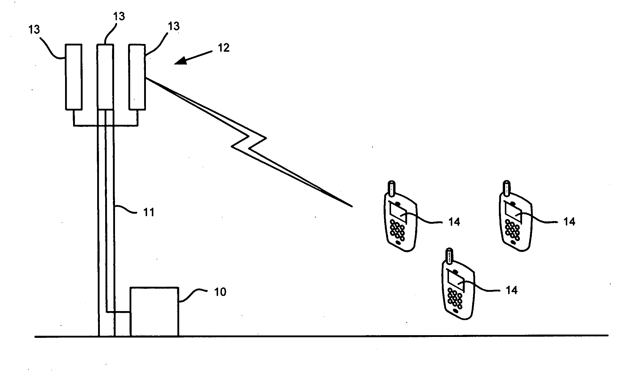
[0006] The exemplary embodiment of the invention provides a method of operating a cellular base station subsystem, the method comprising: modulating a first control data signal to generate a first modulated carrier signal; multiplexing said first modulated carrier signal with a first RF antenna signal onto a feed line; demultiplexing a second RF antenna signal and a second modulated carrier signal from said feed line; demodulating the second modulated carrier signal to generate a second control data signal; analyzing at least one of said signals to generate diagnostic data; and outputting said diagnostic data.
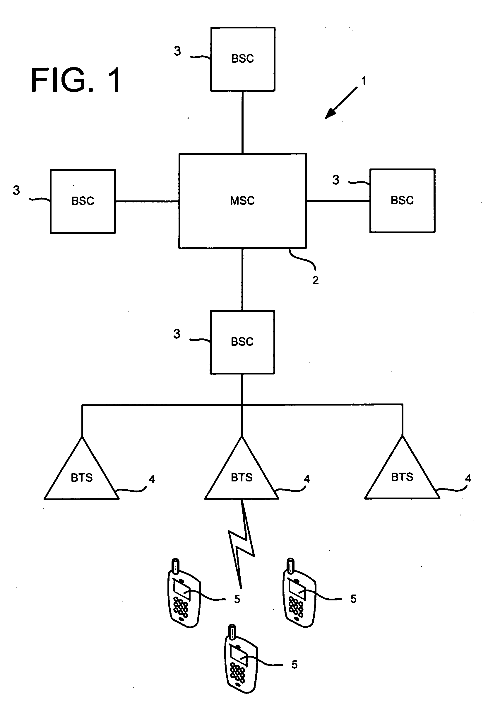
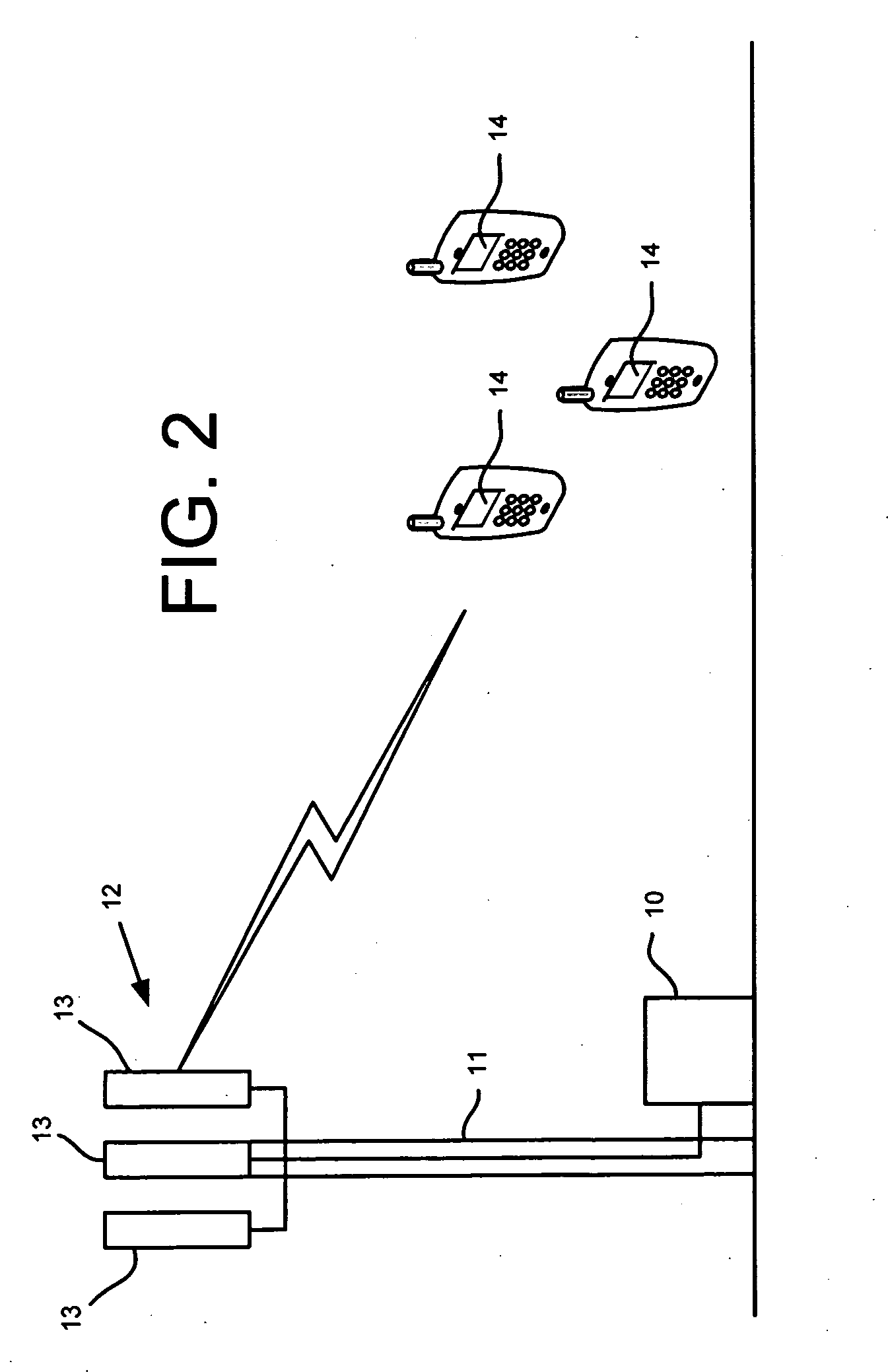
[0007] The exemplary embodiment of the invention further provides a cellular base station subsystem comprising: a modulator adapted to modulate a first control data signal to generate a first modulated carrier signal; a multiplexer adapted to multiplex said first modulated carrier signal with a first RF antenna signal onto a feed line; a demultiplexer adapted to demultiplex a second RF antenna signal and a second modulated carrier signal from said feed line; a demodulator adapted to demodulate the second modulated carrier signal to generate a second control data signal; and a monitor adapted to analyze at least one of said signals to generate diagnostic data and output said diagnostic data.
[0008] The exemplary embodiment of the invention further provides a method of operating a cellular base station subsystem, the method comprising: modulating a first control data signal to generate a first modulated carrier signal; multiplexing said first modulated carrier signal with a first RF antenna signal onto a feed line; demultiplexing a second RF antenna signal and a second modulated carrier signal from said feed line; demodulating the second modulated carrier signal to generate a second control data signal; requesting data from said subsystem; and providing data from a memory of said subsystem in response to the request.
[0009] The exemplary embodiment of the invention further provides a cellular base station subsystem comprising: a modulator adapted to modulate a first control data signal to generate a first modulated carrier signal; a multiplexer adapted to multiplex said first modulated carrier signal with a first RF antenna signal onto a feed line; a demultiplexer adapted to demultiplex a second RF signal and a second modulated carrier input signal from said feed line; a demodulator adapted to demodulate the second modulated carrier signal to generate a second control data signal; and an addressable memory adapted to provide data on request from said subsystem.

Problems solved by technology

However, the optimum value of downtilt is not always predictable prior to actual installation and testing.

Method used


Image

  • Cellular base station subsystem
  • Cellular base station subsystem
  • Cellular base station subsystem

Examples


Embodiment Construction

[0006] The exemplary embodiment of the invention provides a method of operating a cellular base station subsystem, the method comprising: modulating a first control data signal to generate a first modulated carrier signal; multiplexing said first modulated carrier signal with a first RF antenna signal onto a feed line; demultiplexing a second RF antenna signal and a second modulated carrier signal from said feed line; demodulating the second modulated carrier signal to generate a second control data signal; analyzing at least one of said signals to generate diagnostic data; and outputting said diagnostic data.

[0007] The exemplary embodiment of the invention further provides a cellular base station subsystem comprising: a modulator adapted to modulate a first control data signal to generate a first modulated carrier signal; a multiplexer adapted to multiplex said first modulated carrier signal with a first RF antenna signal onto a feed line; a demultiplexer adapted to demultiplex a ...


PUM


Abstract

A method of operating a cellular base station subsystem such as a smart bias tee. The method comprising: modulating a first control data signal to generate a first modulated carrier signal; multiplexing said first modulated carrier signal with a first RF antenna signal onto a feed line; demultiplexing a second RF antenna signal and a second modulated carrier signal from said feed line; demodulating the second modulated carrier signal to generate a second control data signal; analyzing at least one of said signals to generate diagnostic data; and outputting said diagnostic data. The subsystem also has an addressable memory adapted to provide data on request from said subsystem.

Description

FIELD OF THE INVENTION [0001] The present invention is related to a subsystem of a cellular base station. BACKGROUND OF THE INVENTION [0002] Cellular communication systems employ a plurality of antenna systems, each serving a sector or area commonly referred to as a cell. The collective cells make up the total service area for a particular wireless communication network. [0003] Serving each cell is an antenna array and associated switches connecting the cell into the overall communication network. Typically, the antenna array is divided into sectors, where each antenna serves a respective sector. For instance, three antennas of an antenna system may serve three sectors, each having a range of coverage of about 120°. These antennas typically have some degree of downtilt such that the beam of the antenna is directed slightly downwardly towards the mobile handsets used by the customers. This desired downtilt is often a function of terrain and other geographical features. However, the o...

Claims


Application Information

Patent Timeline
Patent Type & Authority Applications(United States)
IPC IPC(8): H04B7/185H04B1/38
CPCH04W88/08
Inventor GRIBBEN, DOUGLAS ALANASBRIDGE, HAROLD EDMOND JR.
Owner ANDREW LLC
Learn More