
Process for selecting objects in a PLM database and apparatus implementing this process

a database and object technology, applied in the field of computerimplemented methods and systems, can solve the problems of time and resources consumption, cripplingly long rendering time of a view of an object, and inability to virtual camera,

Active Publication Date: 2007-07-12
DASSAULT SYSTEMES
View PDF38 Cites 33 Cited by
  • Summary
  • Abstract
  • Description
  • Claims
  • Application Information

AI Technical Summary

Problems solved by technology

One of the problems with PLM solutions is that the users of the system may wish to work on one or more objects such as a part or an assembly of parts of a more complex product, and thus has to select said desired parts to edit, modify, view them, etc.
However, owing to the typical size of a file representing a product in a CAD system (an product such as an airplane is likely to contain millions of parts), the rendering time of a view of said object may be cripplingly long.
In addition, virtual camera is impossible, for similar reasons.
Nevertheless, those methods require all to first load the whole model which is, as seen above, time and resources consuming.

Method used


Image

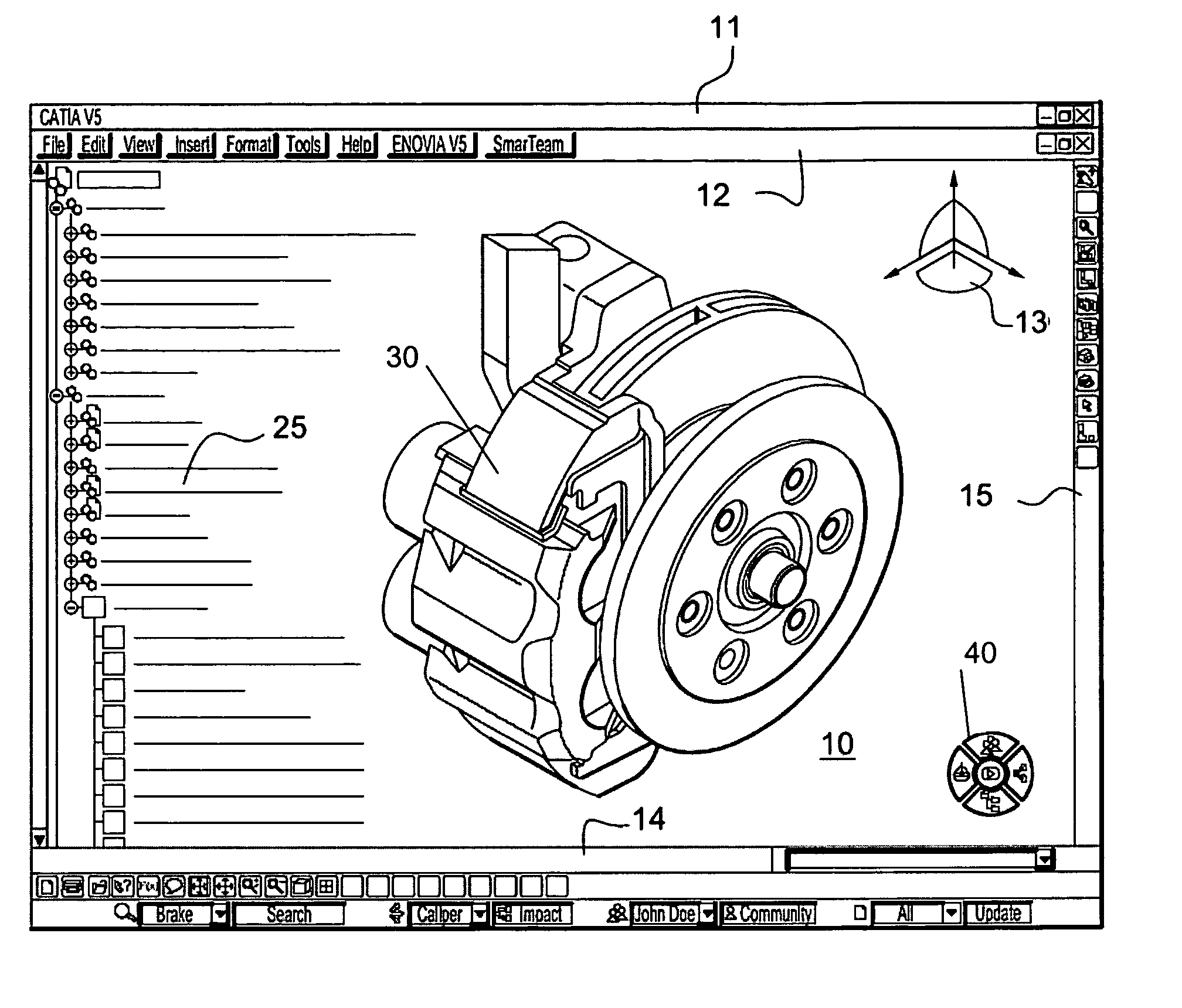
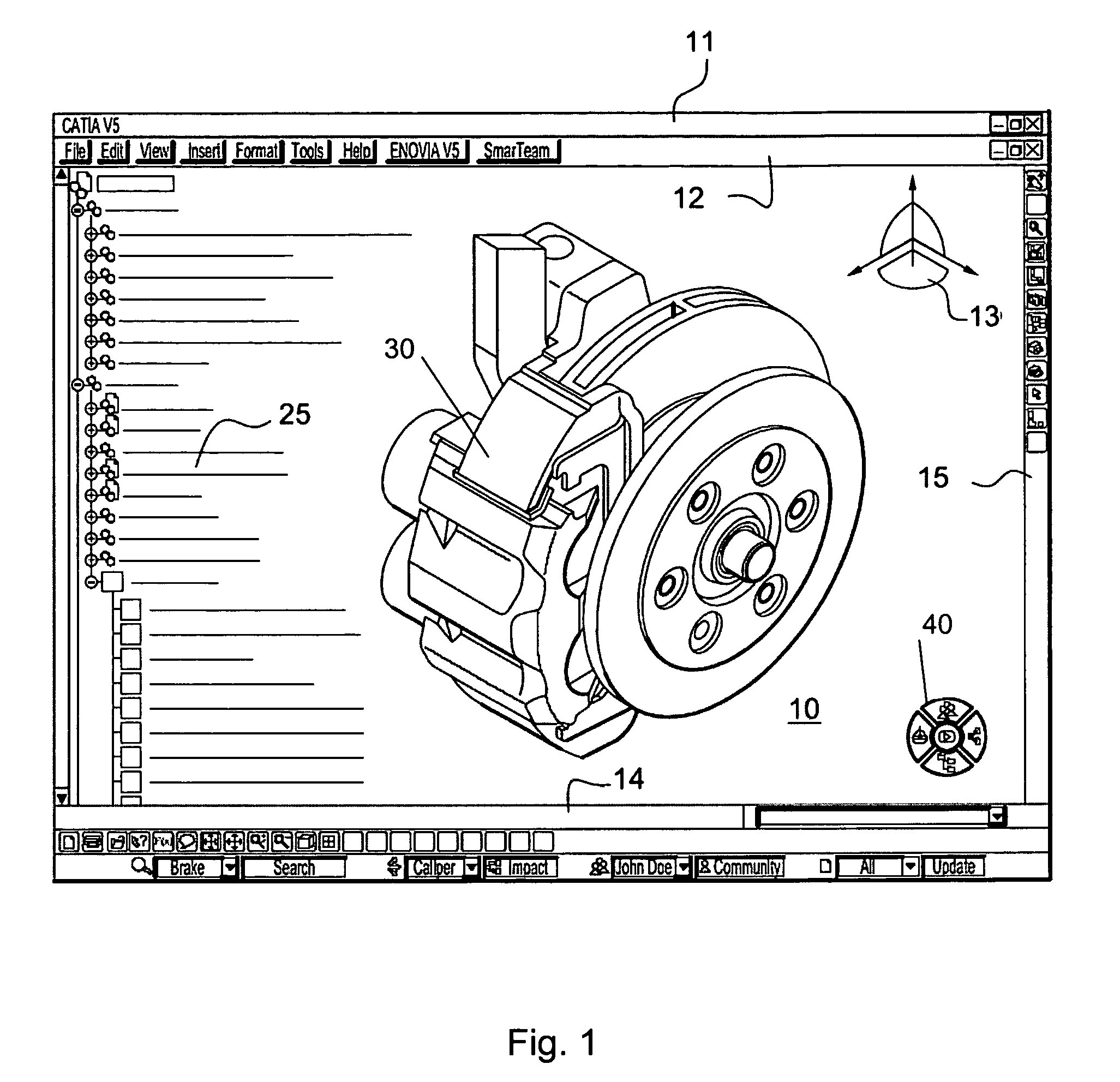
  • Process for selecting objects in a PLM database and apparatus implementing this process
  • Process for selecting objects in a PLM database and apparatus implementing this process
  • Process for selecting objects in a PLM database and apparatus implementing this process

Examples


first embodiment

[0124] In a first embodiment, the user may activate the pointer (through a mouse click for example) on the simplified non-associative view and drag the pointer in order to create a volume such as a sphere. The more the pointer is dragged, the bigger the volume is. Once the pointing device is released (like in a “drag and drop” process), a query to the database is triggered in order to identify all the parts intersecting the sphere using the previously defined bounding boxes (step 640). This enables the user to rapidly, easily and intuitively define a required volume thanks to a graphical feedback of the size of said volume.

second embodiment

[0125] In a second embodiment, the user defines the volume thanks to a dedicated user interface where some pre-defined value are presented to the user, said user being able to modify the values (height, width, radius . . . ). Once the volume is defined and displayed in the non-associative view, queries are triggered in the database to retrieve the exact representations of the identified objects.

third embodiment

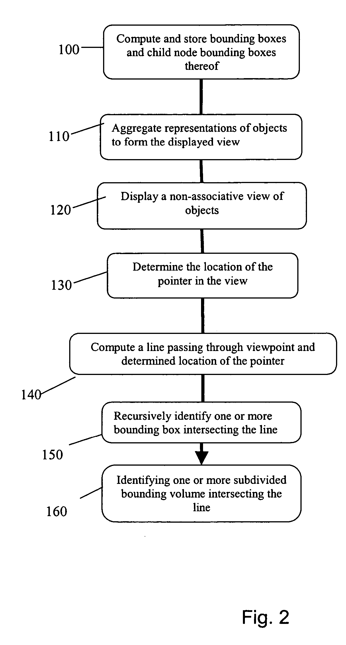
[0126] In a third embodiment, the definition of the volume may use the computed ray previously described (step 140, FIG. 2). Once an object is identified according to the process described in connection with FIGS. 2 to 4, the user may input an offset distance in order to increment the size of the identified object. This way, the user defines a volume that may be used for a next volume query, enabling for example to retrieve all the objects close to the previously identified objects (within a predetermined distance, namely the offset distance).

[0127] Once a set of objects are identified through the process of step 640, said identified objects are for example highlighted and their respective exact representations are retrieved from the database (step 650). Those representations are therefore superimposed on the simplified non-associative representation already displayed. As seen before, in another embodiment of the invention, the exact representations of the identified objects are loa...


PUM


Abstract

The invention is directed to a process, an apparatus and a program for selecting objects in a PLM database containing modeled objects. The invention allows a user to rapidly display a view of the set of objects while allowing for selecting objects in the view, without the need for loading the complete and exact representations of all the objects of the view when the user is looking for particular objects to work on.

Description

RELATED APPLICATION [0001] This application claims priority to European Application No. 05028720.0, filed Dec. 30, 2005. FIELD OF THE INVENTION [0002] The invention relates to the field of computer-implemented methods and systems, and more specifically to product life cycle management solutions, which contain databases of data representative of modeled objects. BACKGROUND OF THE INVENTION [0003] A number of systems and solutions are offered on the market for the design of parts or assemblies of parts, such as the one provided by DASSAULT SYSTEMES under the trademark CATIA. These so-called computer-aided design (CAD) systems allow a user to construct, manipulate and view complex three-dimensional (3D) models of objects or assemblies of objects. CAD systems provide a representation of modeled objects using edges or lines, in certain cases with faces. Lines or edges may be represented in various manners, e.g. non-uniform rational B-splines (NURBS). These CAD systems manage parts or ass...

Claims


Application Information

Patent Timeline
IPC IPC(8): G06T15/20G06F3/048G06F3/0482G06T19/00
CPCG06F3/0482G06F17/50G06F17/30271G06T19/00G06T2200/24G06T17/005G06F9/451G06F16/56G06F30/00G06F17/40G06T11/001G06T15/04G06F3/14G06T15/005
Inventor DELARUE, GUILLAUMENONCLERCQ, ARNAUD
Owner DASSAULT SYSTEMES
Learn More