
Self-aligning collar swaging system for airplane panel bolts

a self-aligning, bolt technology, applied in the direction of manufacturing tools, metal-working machine components, metal-working apparatus, etc., can solve the problems of difficult to accurately align the bolt, the collar and the die, and the cost of wear and tear,

Active Publication Date: 2007-07-12
ELECTROIMPACT
View PDF8 Cites 31 Cited by
  • Summary
  • Abstract
  • Description
  • Claims
  • Application Information

AI Technical Summary

Benefits of technology

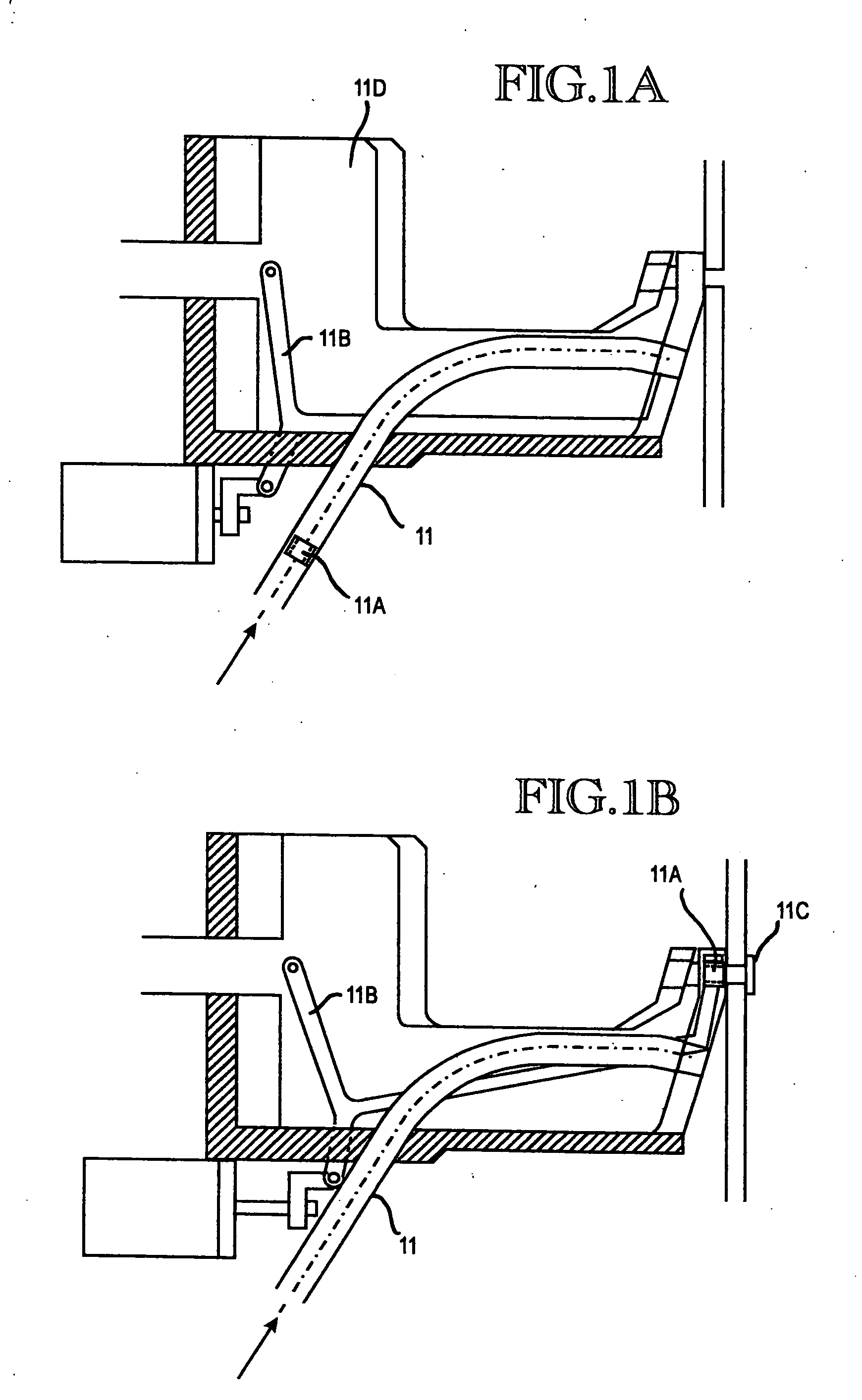
[0009] Another aspect of the present invention is a collar swaging system for use with fasteners in the manufacture of large mechanical assemblies, in which collars are transported to a collar die, comprising: a receiving element at the collar die for stopping the transported collar, wherein the collar is stopped relative to the die by the receiving element and wherein the die is mounted such that the die is moveable longitudinally toward the workpiece and also slightly laterally, such that when the collar is positioned against a workpiece by movement of the die and a fastener is thereafter moved into the positioned collar through an opening in the workpiece, the resulting action of the fastener on the collar causes the collar and the die to move into alignment with the fastener, pressure from the die on the collar against the workpiece preventing pivoting of the collar relative to the longitudinal axis of the fastener.

Problems solved by technology

These known collar gripper systems are, however, often complex, expensive and can wear out or break.
Another disadvantage to gripper systems in general is the difficulty in accurately aligning the bolt, the collar and the die.
Even small misalignments can result in a collar attempting to move onto a bolt in a tipped orientation, causing difficulties in the swaging process and / or delays in manufacturing due to the necessity of removing a damaged or misaligned collar, which is time-consuming.

Method used


Image

  • Self-aligning collar swaging system for airplane panel bolts
  • Self-aligning collar swaging system for airplane panel bolts
  • Self-aligning collar swaging system for airplane panel bolts

Examples


Embodiment Construction

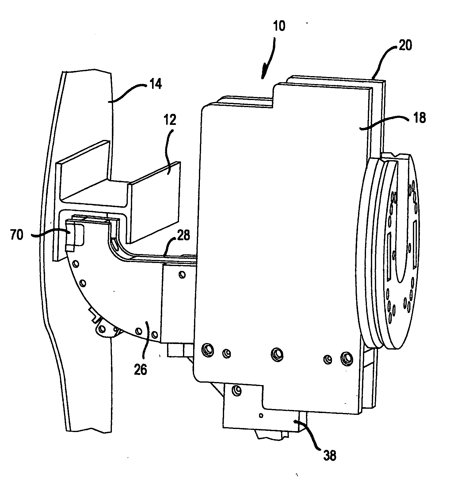
[0025]FIG. 4 shows a collar delivery system used in the manufacture of large scale assemblies, such as commercial aircraft. The collar delivery system is partially defined by a clamp fork / ram combination which, after a collar has been positioned onto a bolt, swages the collar onto the bolt. The clamp fork / ram combination 10 in FIG. 4 is configured to secure an aircraft stringer 12 to a panel 14. The stringer 12 is secured to the panel 14 via a large number of closely spaced bolt / collar combinations. In operation, the clamp fork / ram combination moves automatically along the stringer, securing, in sequence, successive collars onto the exposed ends of successive bolts. Such a clamp fork / ram combination can be used for a variety of applications besides the manufacture of aircraft. Aircraft parts are shown in this application for illustration of one desired use. The clamp fork / ram combination 10 is configured to incorporate a collar delivery system which delivers collars to be positioned...


PUM

PropertyMeasurementUnit
Thicknessaaaaaaaaaa
Pressureaaaaaaaaaa
Sizeaaaaaaaaaa

Abstract

A system and method for feeding collar members to an attachment system for assembly of aircraft and similar large scale mechanical assemblies. Collars are fed sideways along a tube having a rectangular internal cross-section to a collar pathway defined by an clamp fork and swaging ram combination. The collar pathway is curved to present the collar to a receiving element mounted on a swaging die in a proper orientation relative to an attachment bolt which is moved through an opening in the workpiece and then through the collar. As the bolt is moved into the collar, the collar, receiving element and swaging die move together laterally to come into alignment with the bolt.

Description

TECHNICAL FIELD [0001] This invention relates generally to attachment systems and methods of manufacture of large scale assemblies, such as the attachment of panels and stringers in the manufacture of commercial aircraft, and more specifically concerns a system for presenting collars to attachment bolts for swaging thereon or during the attachment / manufacturing process. BACKGROUND OF THE INVENTION [0002] In the manufacture of large commercial aircraft as well as other similar large mechanical assemblies, various parts of the assemblies are secured together with bolts, typically lock bolts, with collar members being swaged on to the ends of the bolts for secure attachment of the parts. Typically, the collar members, which are small hollow cylindrical sections of appropriate internal diameter relative to the bolt, sometimes having a flange, are moved from a storage unit such as a bin or a cartridge, to the exposed end of the bolt, which extends through registered openings in the two p...

Claims


Application Information

Patent Timeline
IPC IPC(8): B23P11/00
CPCB21J15/022B21J15/10B21J15/14B21J15/142B21J15/32Y10T29/53078Y10T29/49947Y10T29/53709Y10T29/53065Y10T29/49908B23P19/006
Inventor TOMCHICK, SCOTT C.ZIEVE, PETER B.BOAD, CARTER L.
Owner ELECTROIMPACT
Learn More