
Ablation catheter with improved tip cooling

a technology of irrigated ablation and catheter, which is applied in the field of irrigated ablation catheter, can solve the problems of ineffective treatment of arrhythmias, no successful outcome, and considerable compromise in quality of life, and achieve the effect of uniform cooling (minimizing turbulent flow and eddies)

Active Publication Date: 2007-07-05
BIOSENSE WEBSTER INC
View PDF5 Cites 55 Cited by
  • Summary
  • Abstract
  • Description
  • Claims
  • Application Information

AI Technical Summary

Benefits of technology

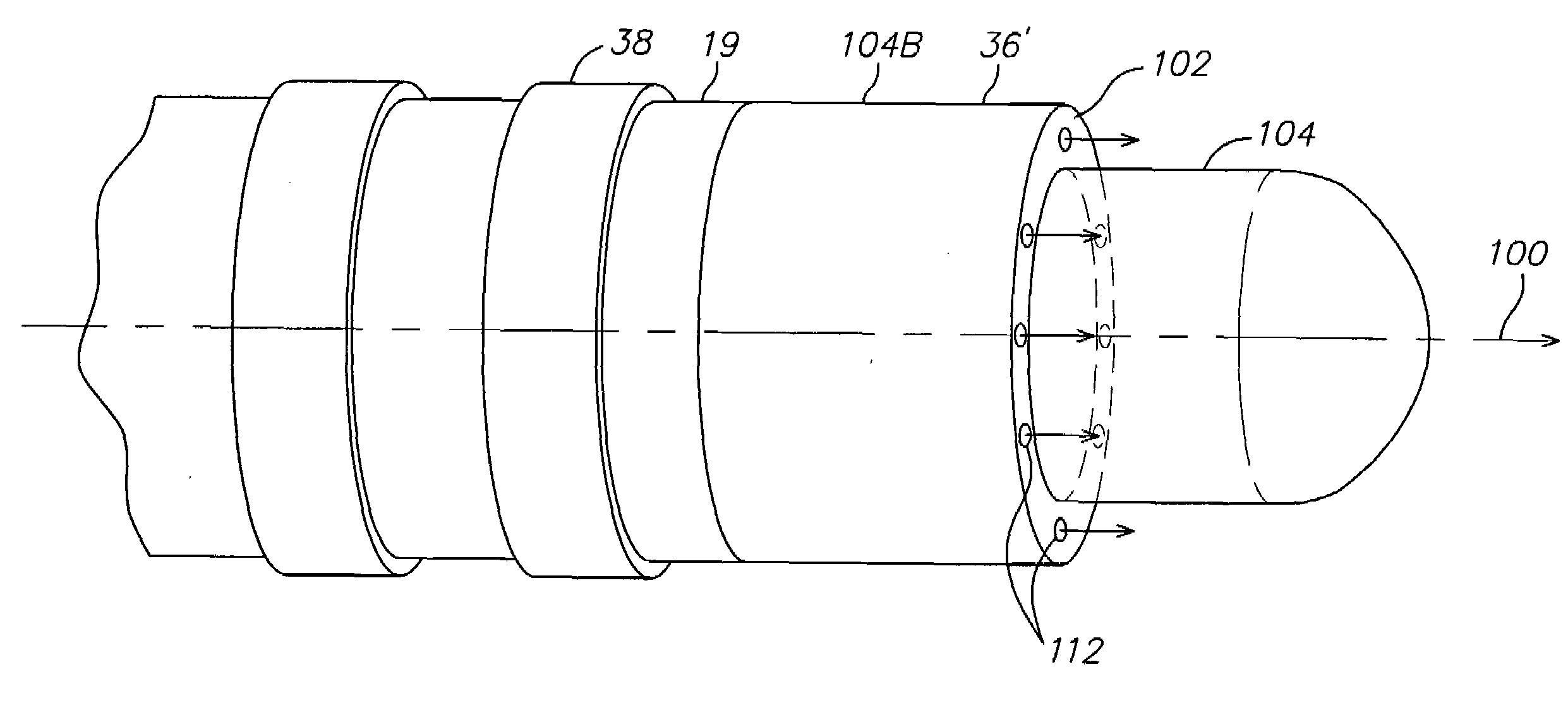
[0008]A catheter in accordance with the present invention includes a catheter body having an outer wall, proximal and distal ends, and at least one lumen extending therethrough. A tip section distal the catheter body includes an irrigated tip electrode and a segment of flexible tubing with at least one lumen therethrough. The tip electrode has a stepped profile which provides laminar flow (or at least minimizes turbulent flow and eddies) of irrigation / cooling fluid over its surface, which in turn provides more uniform cooling of the tip electrode, particularly where the tip electrode is elongated. In one embodiment, the tip electrode has a longitudinal axis, an outer ring surface generally perpendicular to the longitudinal axis, and an outer cylindrical surface extending distally from the outer ring surface along the longitudinal axis. Openings are provided in the outer ring surface to permit fluid (e.g., saline) to pass from an interior of the tip electrode to the outer ring surface and flow in a laminar manner over the cylindrical surface.

Problems solved by technology

A patient may also live with atrial flutter and various forms of tachycardia but quality of life may be considerably compromised.
Other arrhythmias are less effectively treated, requiring more RF lesions for a successful outcome or resulting in no successful outcome.
This causes an impedance rise.

Method used


Image

  • Ablation catheter with improved tip cooling
  • Ablation catheter with improved tip cooling
  • Ablation catheter with improved tip cooling

Examples


Embodiment Construction

[0021]In the following description of the preferred embodiments, reference is made to the accompanying drawings that form a part hereof, and in which is shown by way of illustration a specific embodiment in which the invention may be practiced. It is to be understood that other embodiments may be utilized and structural changes may be made without departing from the scope of the present invention.

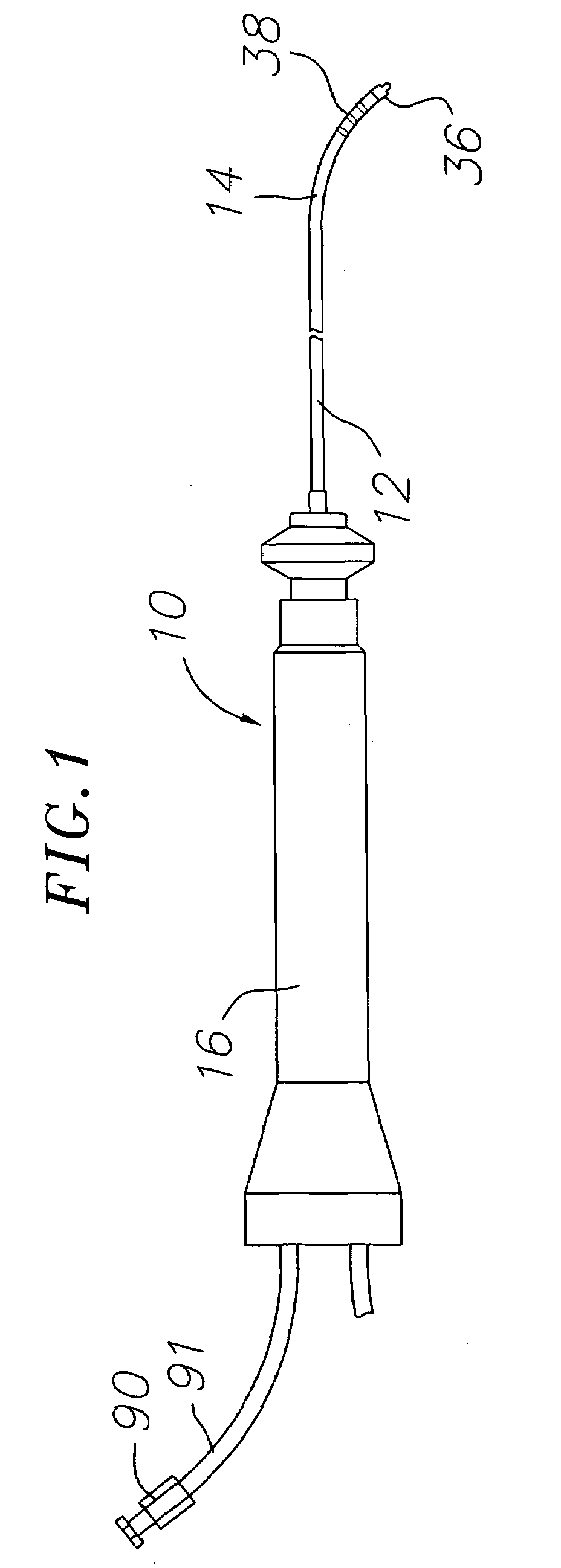
[0022]In an embodiment of the invention, there is provided a deflectable catheter with an irrigated tip having a stepped profile which provides a laminar flow of fluid over the tip surface for more uniform cooling of the tip surface. As shown in FIG. 1, catheter 10 comprises an elongated catheter body 12 having proximal and distal ends, a tip section 14 at the distal end of the catheter body 12, and a control handle 16 at the proximal end of the catheter body 12.

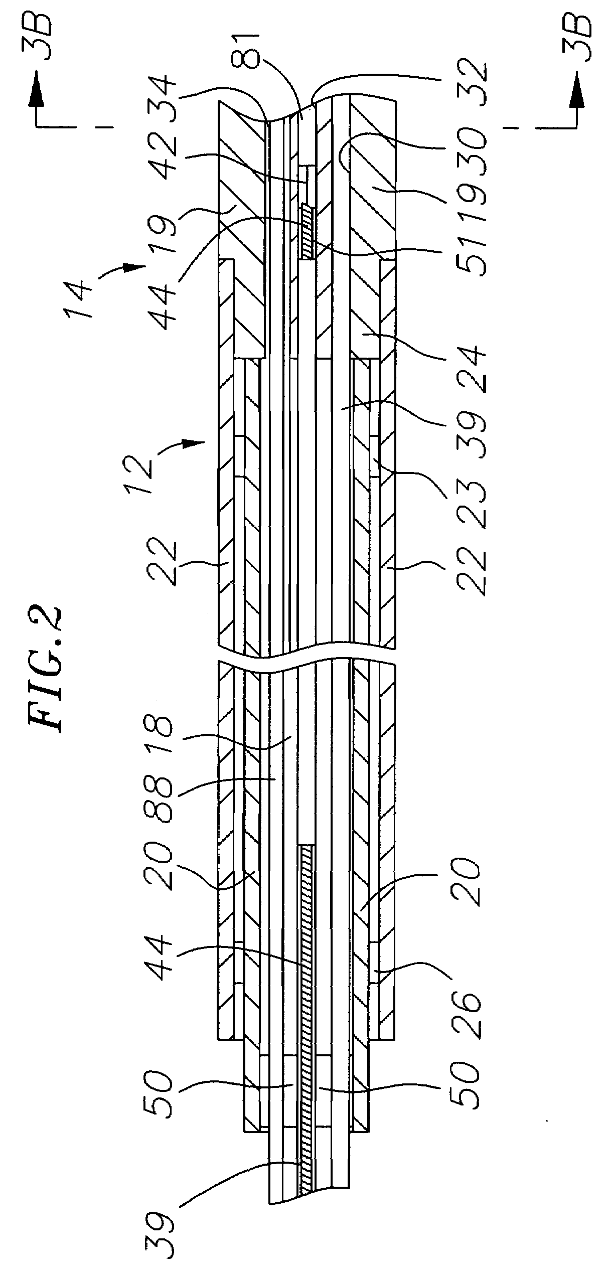
[0023]With reference to FIGS. 1-2, the catheter body 12 comprises an elongated tubular construction having a single, axial or cent...


PUM


Abstract

A catheter has a catheter body having an outer wall, proximal and distal ends, and at least one lumen extending therethrough. A tip section distal the catheter body includes an irrigated tip electrode and a segment of flexible tubing with at least one lumen therethrough. The tip electrode has a stepped profile which provides laminar flow (or at least minimizes turbulent flow and eddies) of irrigation / cooling fluid over its surface, which in turn provides more uniform cooling of the tip electrode, particularly where the tip electrode is elongated. In one embodiment, the tip electrode has a longitudinal axis, an outer ring surface generally perpendicular to the longitudinal axis, and an outer cylindrical surface extending distally from the outer ring surface along the longitudinal axis. Openings are provided in the outer ring surface to permit fluid (e.g., saline) to pass from an interior of the tip electrode to the outer ring surface and flow in a laminar manner over the cylindrical surface.

Description

FIELD OF THE INVENTION[0001]The present invention relates to ablation catheters, and in particular to irrigated ablation catheters with improved cooling of the tip electrode.BACKGROUND OF THE INVENTION[0002]The heart has a natural pacemaker and conduction system which causes the heart muscle to contract, or beat, in an orderly rhythmical manner. The normal pacing rate for an adult at rest is about 60 to 70 beats per minute. There are many physiologic abnormalities which cause one or more chambers of the heart to beat more rapidly (tachycardia or flutter) or chaotically (fibrillation). A patient cannot live with ventricular fibrillation because there would be no blood pumped through the arteries, but may live with atrial fibrillation so long as the chaotic impulses are filtered out at the AV node and do not reach the ventricles. A patient may also live with atrial flutter and various forms of tachycardia but quality of life may be considerably compromised.[0003]Many of these arrhythm...

Claims


Application Information

Patent Timeline
Patent Type & Authority Applications(United States)
IPC IPC(8): A61B18/14
CPCA61B18/1492A61B2218/002A61B2018/00029
Inventor DATTA, KESHAVA
Owner BIOSENSE WEBSTER INC
Learn More