
One Piece, Collapsible PV Assembly

a pv assembly and collapsible technology, applied in the safety of solar heat collectors, lighting and heating equipment, electric generators, etc., can solve the problem of easy installation of light weight pv assemblies, and achieve the effect of maximizing packing density

Inactive Publication Date: 2007-07-05
SUNPOWER CORPORATION
View PDF16 Cites 124 Cited by
  • Summary
  • Abstract
  • Description
  • Claims
  • Application Information

AI Technical Summary

Benefits of technology

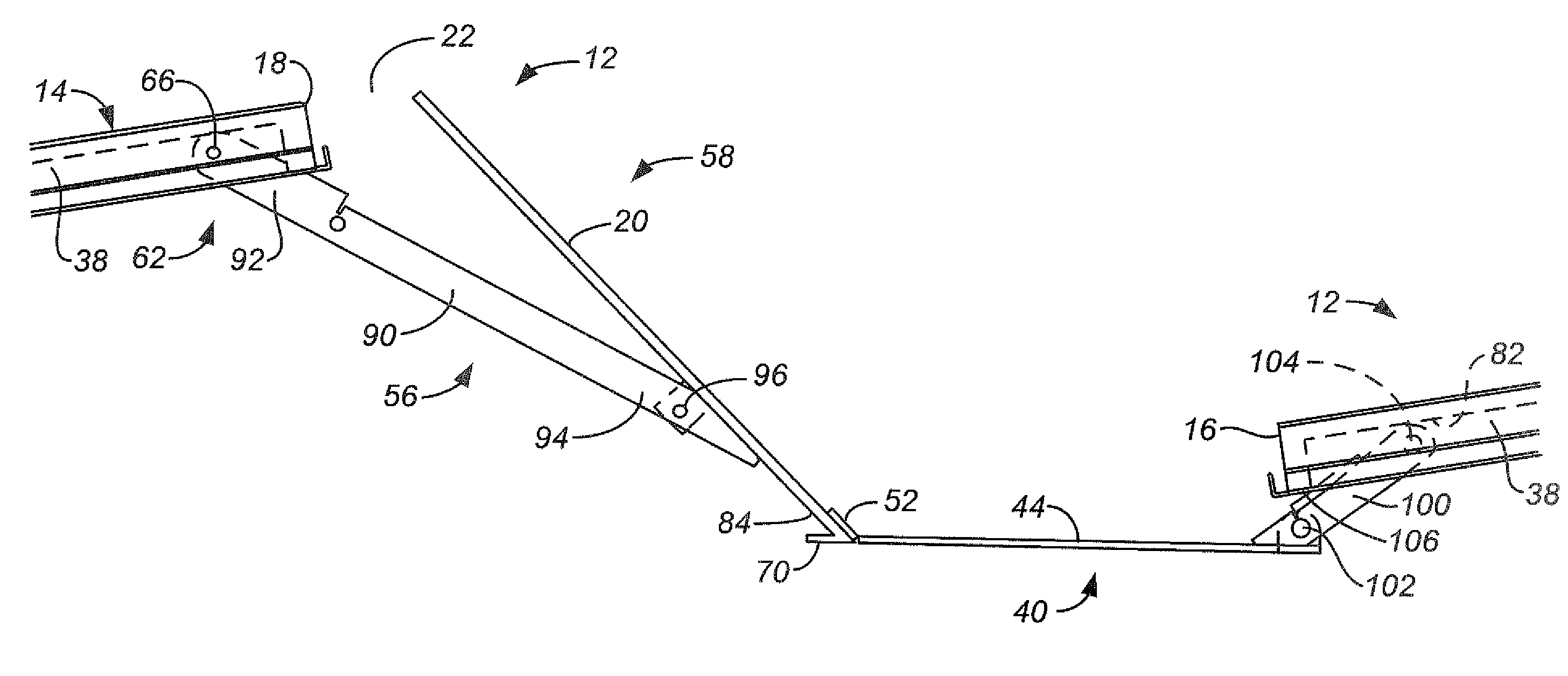
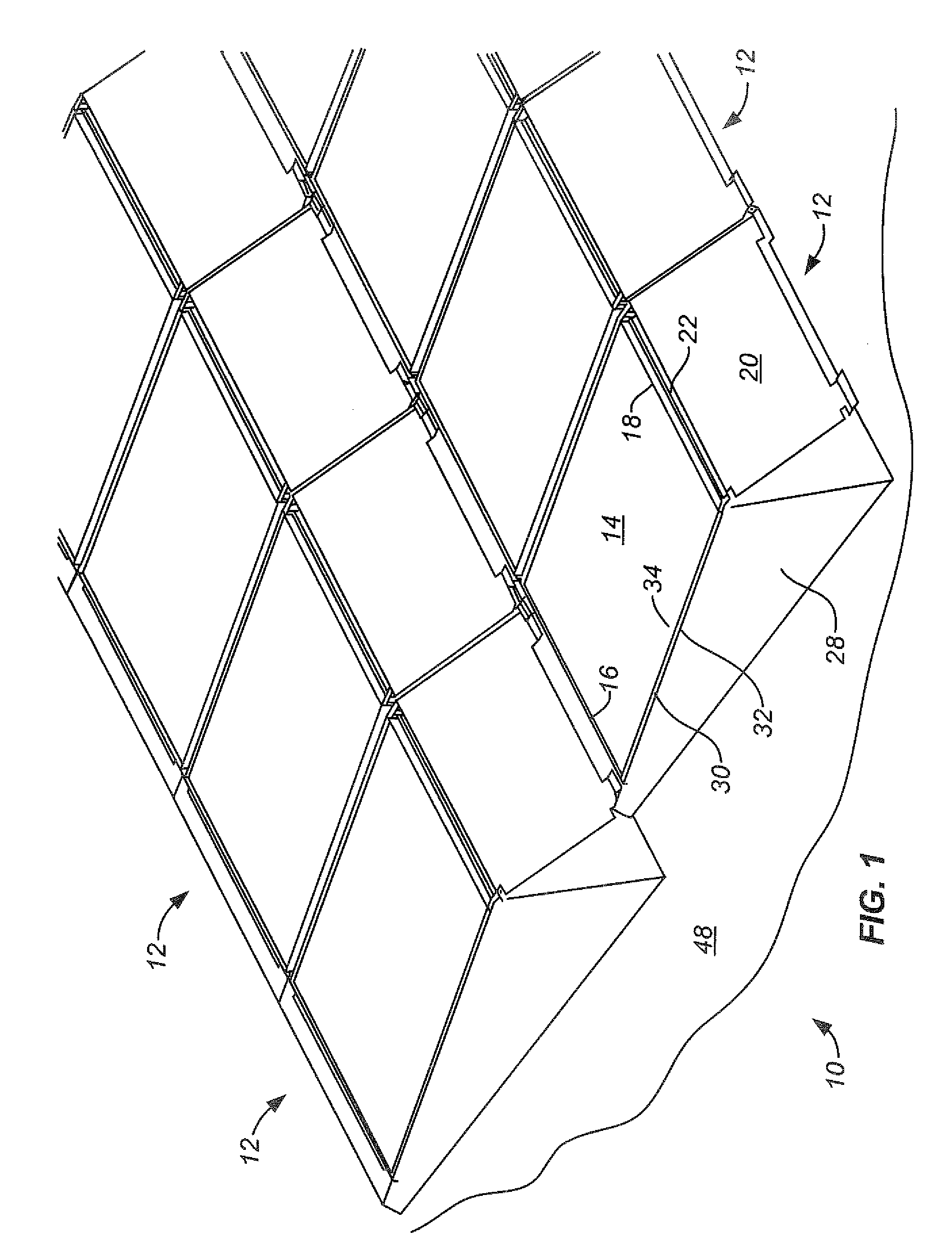
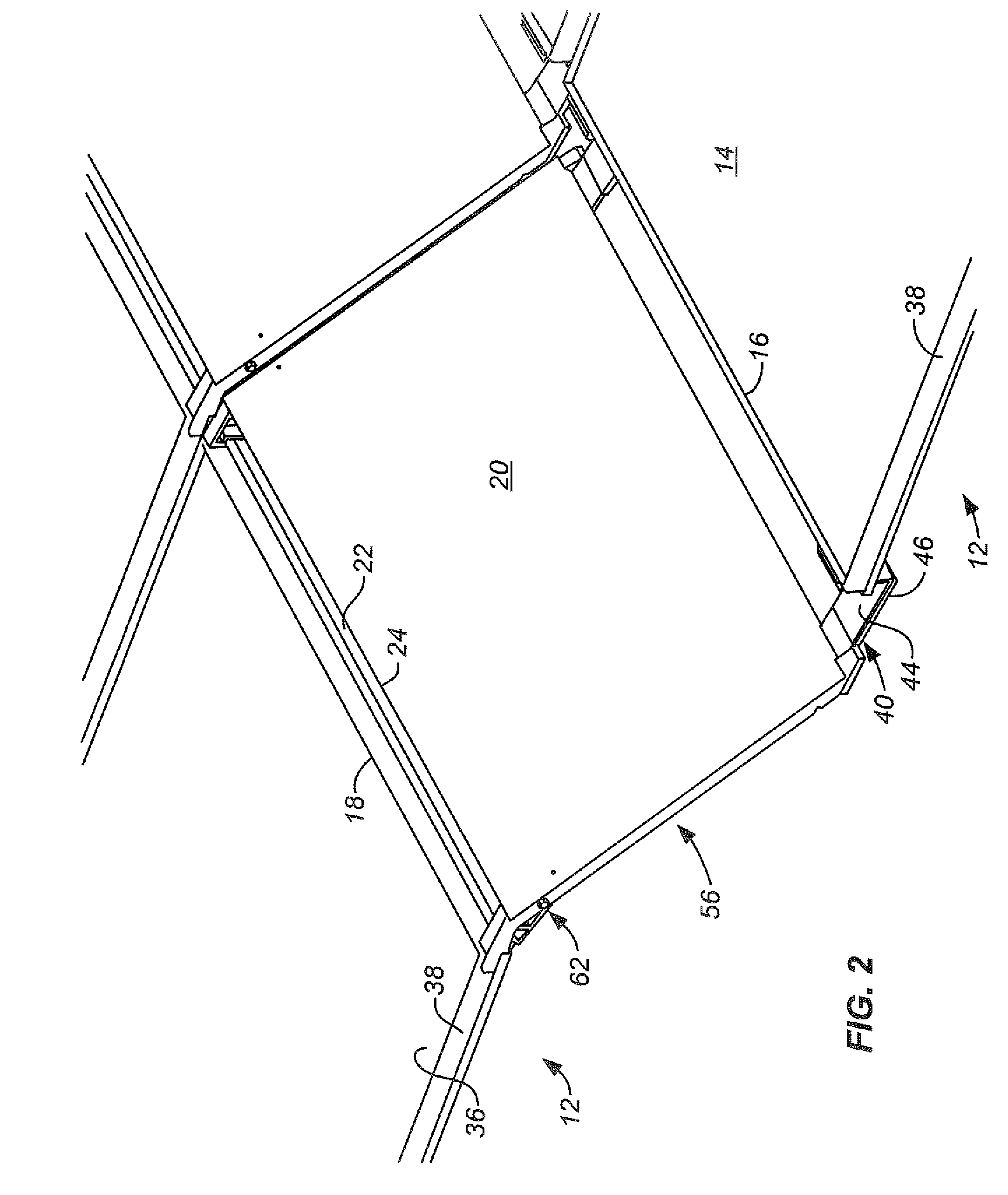
[0008] An example of a one-piece, nesting PV assembly comprises a PV module comprising front and rear edges on opposite sides thereof, an upper surface and a lower surface. A front support is secured to the PV module at the front edge, the front support having a first support-surface-engaging surface, the front support extending outwardly away from the front edge. A rear support assembly comprises any wind deflector assembly having first and second end portions, the wind deflector assembly comprising a wind defector. The second end portion of the wind deflector assembly comprises a second support-surface-engaging surface. The first end portion is secured to the PV module at the rear edge, the rear support assembly extending downwardly and outwardly away from the rear edge. The PV assembly has complementary nestable top and bottom surface profiles to permit first and second of the PV assemblies to stack in a nesting fashion in a transport mode with the PV module, front support and rear support assembly of the first PV assembly adjacent to the corresponding structure of the second PV assembly thereby maximizing packing density.
[0009] One aspect of the present invention is the recognition that there are substantial advantages to be gained from designing a one-piece, collapsible PV assembly that can be shipped to an installation site and mounted directly to a roof or other support surface without the need to assemble the major components, including the rear wind deflector, of the PV assembly, the installation capable of being carried out using simple tools in a straightforward installation process. Another aspect of the present invention is the recognition that there are significant advantages arising from shipping the PV assemblies in a compact folded state, especially where the PV assembly can be shipped in the same shipping container as the PV module.

Problems solved by technology

Fourth, lightweight PV assemblies are easier to install than assemblies that rely on heavy ballast weight to counteract wind uplift forces.

Method used


Image

  • One Piece, Collapsible PV Assembly
  • One Piece, Collapsible PV Assembly
  • One Piece, Collapsible PV Assembly

Examples


Embodiment Construction

[0028] The following description of the invention will typically be with reference to specific structural embodiments and methods. It is to be understood that there is no intention to limit the invention to the specifically disclosed embodiments but that the invention may be practiced using other features, elements, methods and embodiments. Preferred embodiments are described to illustrate the present invention, not to limit its scope, which is defined by the claims. Those of ordinary skill in the art will recognize a variety of equivalent variations on the description that follows. Like elements in various embodiments are commonly referred to with like reference numerals.

[0029]FIGS. 1 and 2 disclose a PV installation 10 including an array of one-piece, collapsible PV assemblies 12. Assemblies 12 each include a sloped PV module 14. Sloped PV modules 14 are typically oriented to face the sun. That is, in the northern hemisphere, the lower, front edge 16 of PV module 14 may be consid...


PUM


Abstract

A collapsible PV assembly comprises a PV module, a front support and a rear support assembly. The front and rear supports are secured to the front and rear edges of the PV module. The rear support assembly comprises a wind deflector assembly including a wind deflector which can be placed in a downwardly and outwardly extending use orientation and a storage orientation, extending along the lower surface of the PV module. In some embodiments the wind deflector assembly is pivotally connected to the PV module.

Description

CROSS-REFERENCE TO OTHER APPLICATIONS [0001] This application claims the benefit of provisional patent application No. 60 / 754,912 filed 29 Dec. 2005 and entitled One Piece, Collapsible PV Assembly.STATE SPONSORED RESEARCH OR DEVELOPMENT [0002] This invention was made with State of California support under the California Energy Commission Agreement Number 500-00-034. The Energy Commission has certain rights to this invention.BACKGROUND OF THE INVENTION [0003] Air moving across an array of photovoltaic (PV) assemblies mounted to the roof of a building, or other support surface, creates wind uplift forces on the PV assemblies. Much work has been done in the design and evaluation of arrays of PV assemblies to minimize wind uplift forces. See U.S. Pat. Nos. 5,316,592; 5,505,788; 5,746,839; 6,061,978; 6,148,570; 6,495,750; 6,534,703; 6,501,013 and 6,570,084. Reducing wind uplift forces provides several advantages. First, it reduces the necessary weight per unit area of the array. This red...

Claims


Application Information

Patent Timeline
IPC IPC(8): H02N6/00
CPCF24J2/4638F24J2/5239F24J2/526F24J2002/5277H02S20/24Y02E10/47Y02E10/50H02S20/00H02S20/23Y02B10/12F24S25/16F24S25/65F24S40/85F24S2025/012H02S30/20Y02B10/10
Inventor MASCOLO, GIANLUIGIDINWOODIE, THOMAS L.
Owner SUNPOWER CORPORATION
Learn More